
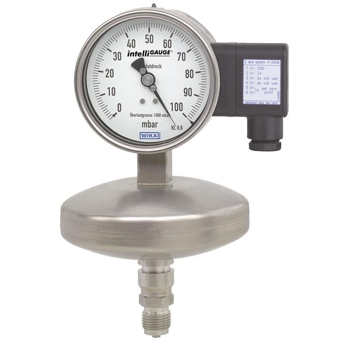
Absolute pressure gauge with output signal
Description
The model APGT43 intelliGAUGE ® (patent, property right: e.g. DE 202007019025) can be used wherever pressure measurement has to be independent of fluctuations in the atmospheric pressure. The instrument serves for the on-site display with a simultaneous signal transmission to a central control or remote centre.
The model APGT43 is based upon a model 532.54 high-quality, stainless steel pressure gauge, manufactured in
accordance with DIN 16002.
The intelliGAUGE ® model APGT43 fulfils all safety-related requirements of the relevant standards and regulations for the on-site display of the working pressure of pressure vessels.
The robust diaphragm measuring system produces a pointer rotation proportional to the pressure.
for further approvals see page 5
intelliGAUGE ® model APGT43
An electronic angle encoder, proven in safety-critical automotive applications, determines the position of the pointer shaft - it is a non-contact sensor and therefore completely free from wear and friction. From this, the electrical output signal proportional to the pressure, e.g. 4 ... 20 mA, is produced. The measuring span (electrical output signal) is adjusted automatically along with the mechanical display, i.e. the scale over the full display range corresponds to 4 ... 20 mA. The electrical zero point can also be set manually.
The electronic WIKA sensor, integrated into the high-quality absolute pressure gauge, combines the advantages of electrical signal transmission with a local mechanical display that remains readable during a power failure. An additional measuring point for mechanical pressure
display can thus be saved.
Special features
- No configuration necessary due to “plug-and-play”
- Scale ranges from 0 … 25 mbar absolute pressure
- Easy-to-read analogue display with nominal sizes 100 and 160
- High overload safety, long service life due to metallic media chamber sealing
- Media chamber protected against unauthorised access
Build a APGT43.1X0 for your task
The article number is assembled automatically. If unsure — ask an engineer; we'll match the line's parameters.
- Nominal size100
- Output signal4 ... 20 mA, 2-wire
- Explosion protectionwithout
- Unitmbar absolute
- Scale range—
- 2nd Scale or Special Scalewithout
- Process connection—
- Connection locationlower mount
- Diaphragm Material—
- Mounting devicewithout
- Liquid Damping (case filling)—
- Electrical connectionL-Plug DIN EN 175201-804 6-pin + PE sidewise
- Special design featureswithout
Finish your configuration
Select every option to submit the request.
| Model | APGT43 |
| Product family | APGT |
| Subcategory | Absolute pressure gauge with output signal |
| Pressure ranges | 0…25 bar · 0…25 mbar · 0…25000 mbar · 0…0.36 psi · 0…3600 psi |
| Accuracy class | 2.5 |
| Accuracy standard | DIN 16002 |
| Process connection | Open connecting flange DN 25 PN 25 per EN 1092-1, form BOpen connecting flange DN 25 PN 25, DIN 2501, form D per DIN 2526Small flange for vacuum applications DN 10Small flange for vacuum applications DN 16G ½ B½ NPT½ NPT femaleG1/2B1/2NPT1/2NPT femaleDN25 PN25DN10DN16 |
| Process temperature | −20…+200 °C |
| Output signal | 4-20mA · 0-20mA · 0-10V |
| Power supply | 12...30 V DC |
| Electrical connection | Cable socket PA 6, black; Cable gland M20 x 1.5; 6 screw terminals + PE |
| Case material | Stainless steel |
| Wetted parts material | Stainless steel 316Ti, NiCr alloy (Inconel), Monel (option), Stainless steel 316L, Monel |
| Ambient temperature | −40…+60 °C |
| IP rating | IP54 |
| Weight | 1.2 kg |
| Certifications | CERoHSEACGOSTCRNATEXIECExKazInMetrMTSCHSUkrSEPRODNOPUzstandard |
| Explosion protection | [II 2G Ex ia IIC T6/T5/T4 Gb][II 2D Ex ia IIIB T85°C/T100°C/T135°C Db][Ex ia IIC T6/T5/T4 Gb][Ex ia IIIB T85°C/T100°C/T135°C Db]ATEX: II 2G Ex ia IIC T6/T5/T4 Gb, II 2D Ex ia IIIB T85°C/T100°C/T135°C DbIECEx: Ex ia IIC T6/T5/T4 Gb, Ex ia IIIB T85°C/T100°C/T135°C DbEx ia IIC T6/T5/T4 GbEx ia IIIB T85°C/T100°C/T135°C Db |
| Dial size | 100 mm |
| Datasheet languages | EN, DE |
| Model APGT43 | ||
|---|---|---|
| Design | Mechanical absolute pressure measuring instrument per DIN 16002 | |
| Nominal size inmm | ■ 100 ■ 160 | |
| Accuracy class | 2.5 Option: 1.6 ¹⁾ The measurement accuracy is ensured for ambient pressure fluctuations between 955 and 1,065 mbar (min. and max. of atmospheric pressure) | |
| Scale ranges | 0 ... 25 mbar to 0 ... 25 bar absolute pressure [0 ... 0.36 psi to 0 ... 3,600 psi absolute pressure] | |
| Scale | Single scale Option: Dual scale | |
| Pressure limitation | ||
| Steady | Full scale value | |
| Fluctuating | 0.9 x full scale value | |
| Overload safety | 10 x full scale value, max. 25 bar absolute pressure, min. 1 bar absolute pressure Option: 20 x full scale value, max. 25 bar absolute pressure, min. 1 bar absolute pressure | |
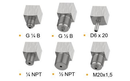
| Process connection with lower measuring flange | ■ G½B ■ ½NPT ■ ½NPTfemale ■ Open connecting flange DN 25 PN 25 per EN 1092-1, form B ■ Open connecting flange DN 25 PN 25, DIN 2501, form D per DIN 2526 ■ Small flange for vacuum applications DN 10 ■ Small flange for vacuum applications DN 16 Further threaded connections and open connecting flanges on request | |
| Permissible temperature ²⁾ | ||
| Medium | +100 °C [+212 °F] maximum Option: +200 °C [+392 °F] maximum | |
| Ambient | -20 ...+60 °C [-4 ... 140 °F] Option: -40 ...+60 °C (silicone oil filling) ¹⁾ | |
| Temperature effect | When the temperature of the measuring system deviates from the reference temperature (+20 °C): max. ±0.8 %/10 K of full scale value | |
| Case | Safety version S3 per EN 837:With solid baffle wall (Solidfront) and blow-out back Instruments with liquid filling with compensating valve to vent case | |
| Case filling | Without Option: With silicone oil M50 case filling, ingress protection IP65 | |
| Wetted materials | ||
| Diaphragm element (pressure element) | ≤ 0.25 bar: Stainless steel 316Ti > 0.25 bar: NiCr alloy (Inconel) | Option: Wetted parts from Monel 1) |
| Media chamber with process connection | Stainless steel 316L |
| Non-wetted materials | |
|---|---|
| Case, movement, bayonet ring | Stainless steel |
| Dial | Aluminium, white, black lettering |
| Instrument pointer | Aluminium, black |
| Set pointer | Aluminium, red |
| Window | Laminated safety glass |
| Ingress protection per IEC/EN 60529 | IP54 Option: IP65 |
| Mounting | Rigid measuring lines Option: ■ Panel or surface mounting flange ■ Instrument mounting bracket for wall or pipe mounting |
| Model APGT43 | |
|---|---|
| Output signal | Variant 1: 4 …20mA, 2-wire, passive, per NAMUR NE 43 Variant 2: 4 ... 20 mA, 2-wire, for hazardous areas Variant 3: 0 ... 20 mA, 3-wire Variant 4: 0 ... 10 V, 3-wire |
| Supply voltage U B | DC 12V < U B ≤ 30V (variant 1 and 3) DC 14V < U B ≤ 30V (variant 2) DC 15V < U B ≤ 30V (variant 4) |
| Influence of supply voltage | ≤ 0.1 %of full scale/10V |
| Permissible residual ripple of U B | ≤ 10 %ss |
| Permissible max. load R A | Variant 1, 2, 3:R A ≤ (U B - 12 V)/0.02 A with R A in Ωand U B in V, however max.600Ω Variant 4:R A = 100 kΩ |
| Effect of load (variant 1, 2, 3) | ≤ 0.1 %of full scale |
| Impedance at voltage output | 0.5Ω |
| Electrical zero point | Through a jumper across terminals 5 and 6 (see operating instructions) |
| Long-term stability of electronics | < 0.3 %of full scale per year |
| Electr. output signal | ≤ 1 %of measuring span |
| Linear error | ≤ 1 %of measuring span (terminal method) |
| Resolution | 0.13 %of full scale (10 bit resolution at 360°) |
| Refresh rate (measuring rate) | 600 ms |
| Electrical connection | Cable socket PA 6, black PerVDE 0110 insulation group C/250V Cable gland M20 x 1.5 Strain relief 6 screw terminals + PE for conductor cross-section 2.5 mm² |
| Designation of connection termi- nals, 2-wire (variant 1 and 2) | Do not use this terminal U B +/I+ Terminals 3 and 4: For internal use only Terminals 5 and 6: Reset zero point |
| Designation of connection terminals for 3-wire (variant 3 and 4), see operating instructions | +0V/GND |
| Logo | Description | Country |
|---|---|---|
| EU declaration of conformity ■ EMCdirective ■ Pressure equipment directive ■ RoHS directive ■ ATEX directive (option) Hazardous areas - Ex ia Gas [II 2G Ex ia IIC T6/T5/T4 Gb] Dust [II 2D Ex ia IIIB T85°C/T100°C/T135°C Db] | European Union | |
| IECEx (option) Hazardous areas - Ex ia Gas [Ex ia IIC T6/T5/T4 Gb] Dust [Ex ia IIIB T85°C/T100°C/T135°C Db] | International | |
| EAC (option) ■ EMCdirective ■ Pressure equipment directive ■ Low voltage directive ■ Hazardous areas | Eurasian Economic Community | |
| GOST (option) Metrology, measurement technology | Russia | |
| KazInMetr (option) Metrology, measurement technology | Kazakhstan | |
| - | MTSCHS (option) Permission for commissioning | Kazakhstan |
| UkrSEPRO (option) Metrology, measurement technology | Ukraine | |
| DNOP (MakNII) (option) Hazardous areas | Ukraine | |
| Uzstandard (option) Metrology, measurement technology | Uzbekistan | |
| - | CRN Safety (e.g. electr. safety, overpressure, ...) | Canada |
View all (5)
| NS | Scale range | Dimensions inmm | Weight in | |||||||||||
|---|---|---|---|---|---|---|---|---|---|---|---|---|---|---|
| in bar | a | b | c | d 1 | d 2 | D 1 | D 2 | e | f | G | h ±1 | SW | kg | |
| 100 | ≤ 0 ... 250 mbar | 25 | 59.5 | 94 | 133 | 26 | 101 | 99 | 17 | 58 | G½B | 185 | 22 | 1.8 |
| 100 | > 0 ... 250 mbar | 25 | 59.5 | 94 | 76 | 26 | 101 | 99 | 17 | 66 | G½B | 177 | 22 | 1.2 |
| 160 | ≤ 0 ... 250 mbar | 25 | 65 | 124 | 133 | 26 | 161 | 159 | 17 | 58 | G½B | 215 | 22 | 2.3 |
| 160 | > 0 ... 250 mbar | 25 | 65 | 124 | 76 | 26 | 161 | 159 | 17 | 66 | G½B | 207 | 22 | 1.6 |
Couldn't find the answer in the documentation? An engineer will reply within a business day.
Ask an engineer →162 standard articles of family APGT
If you know the code — pick directly. If not — use the configurator in mode “01”.