
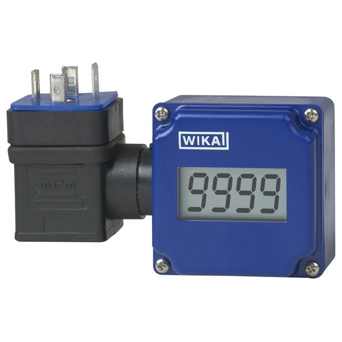
Attachable indicator for transmitters
Description
The model A-AI-1 and A-IAI-1 attachable indicators are the ideal solution for an on-site display with simultaneous signal transmission.
Due to its open programmability and easy installation, even for transmitters already in service, the attachable indicator can be easily and quickly added without difficulty. An additional power supply is not necessary. An additional power supply is not necessary.
The instrument is configured using three buttons which are located under the front cover. A logically structured menu guides the operator through all the necessary programming steps using simple characters on the LCD panel. It is possible to set the indication range and both offset and slope correction. In addition, if required, a filter can be activated and set in various stages. The filter suppresses short spikes and thus enables the easy readability of the display.
Attachable indicator model A-AI-1
All programmed parameters are stored in an EEPROM and are preserved in the event of power outage.
The model A-IAI-1 attachable indicator has been developed specifically for use in hazardous areas. This attachable indicator can be combined with Ex transmitters and also with a repeater power supply (e. g. model IS Barrier) or an Ex galvanic isolator, thus enabling its use in zone 1 areas.
The attachable indicator has its own integrated self-diagnostics, which continuously monitors that the key components of the instrument are working properly. The integrated self-diagnostics, as well as the reporting of an over-range or under-range condition, ensure high operational safety.
With its robust and compact plastic case, the attachable indicator fulfills the ingress protection IP65 and is thus exceptionally suitable for a wide range of industrial applications.
Special features
- Indication range: -1999 ... 9999
- Attachable to transmitter with 4 ... 20 mA output and angular connector to DIN 175301-803 A
- Scalable on-site without external tools
- Ingress protection IP 65
- Ex version II 2G Ex ia/ib IIC/IIB T4 (model A-IAI-1)
Build a A-XI-1 for your task
The article number is assembled automatically. If unsure — ask an engineer; we'll match the line's parameters.
- Model—
- operating of the unitvia keys inside the case
- Instrument configurationwithout, configuration by the customer
Finish your configuration
Select every option to submit the request.
| Model | A-AI-1 |
| Product family | A-AI |
| Subcategory | Attachable indicator |
| Accuracy class | ± 0.2 % of measuring span ± 1 digit |
| Output signal | 4-20 mA |
| Power supply | 4 ... 20 mA loop powered |
| Electrical connection | 4-pin + 1 angular connector per DIN 175301-803 A |
| Case material | ABS, polycarbonate |
| Sealing material | blue profile sealing, profile sealing |
| Ambient temperature | −20…+50 °C |
| IP rating | IP65 |
| Weight | 0.08 kg |
| Certifications | CERoHSATEX |
| Explosion protection | Ex ia IIC/IIB T4 GbEx ib IIC/IIB T4 GbII 2G Ex ia IIC/IIB T4 GbII 2G Ex ib IIC/IIB T4 Gb |
| Datasheet languages | EN |
| Display | |
|---|---|
| Principle | 7-segment LCD, 4-digit, character size10mm |
| Indication range | -1999 ... 9999 |
| Accuracy | ± 0.2 %of measuring span ± 1 digit |
| Measuring rate | 5 measurements/s |
| Voltage supply | |
| Electrical connection | To transmitter with 4 ... 20 mAoutput and angular connector per DIN 175301-803 A. |
| Power supply | Not required, since the attachable indicator is powered by the 4 ... 20 mAloop |
| Voltage drop | Approx.DC 2V |
| Permissible current carrying capacity | Max. 25 mA(40 mAshort term) |
| Logo | Description | Country |
|---|---|---|
| EU declaration of conformity ■ EMCdirective ■ RoHS directive | European Union |
| Display | |
|---|---|
| Principle | 7-segment LCD, 4-digit, character size10mm |
| Indication range | -1999 ... 9999 |
| Accuracy | ± 0.2 %of measuring span ± 1 digit |
| Measuring rate | 5 measurements/s |
| Voltage supply | |
| Electrical connection | To intrinsically safe transmitter with 4 ... 20 mAoutput and angular connector per DIN 175301-803 A. |
| Power supply | Not required, since the attachable indicator is powered by the 4 ... 20 mAloop |
| Voltage drop | Approx.DC 3V |
| Permissible current carrying capacity | Max. 25 mA(40 mAshort term) |
| Logo | Description | Country |
|---|---|---|
| EU declaration of ■ EMCdirective ■ RoHS directive ■ ATEX directive Hazardous areas - Ex i Zone 1 | conformity gas [II 2G Ex ia IIC/IIB T4 Gb] [II 2G Ex ib IIC/IIB T4 Gb] | European Union |
View all (5)
| Model | Ordernumber |
|---|---|
| A-AI-1, standard version | 7082534 |
| A-IAI-1, version with explosion protection (II 2G Ex ia/ib IIC/IIB T4) | 7148512 |
Couldn't find the answer in the documentation? An engineer will reply within a business day.
Ask an engineer →2 standard articles of family A-AI
If you know the code — pick directly. If not — use the configurator in mode “01”.