
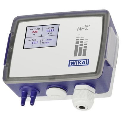
Differential pressure air flow sensor
Description
The model A2G-520 measures the pressure difference on components such as ventilators or pitot tubes, e.g. model A2G-FM, and calculates the air flow using the calibration factor (K factor). By selecting the respective component manufacturer in the menu, the correct calculation formula is automatically taken into account.
To further optimise the air flow measurement under extreme ambient conditions such as altitude and high medium temperature, suitable sensors can be directly integrated.
The piezoresistive measuring element is temperaturecompensated and particularly stable over the long term. It records even the smallest pressure differences and thus ensures high reliability and the highest measurement accuracy. The measured values are available as analogue voltage and current signals, digitally via the RS-485 interface using Modbus ® RTU or via LoRaWAN ® (LPWAN).
Special features
- Integrated air flow calculation based on all common formulas
- Optimisation of air flow measurement through additional pressure and/or temperature compensation
- IIoT-ready and future-proof thanks to analogue and digital signal transmission (Modbus ® ) as well as wireless (LoRaWAN ® )
- Time-saving instrument configuration and display of current measured values on the smartphone via NFC or WIKA app
- Precise measuring results, even under extreme ambient conditions
Build a A2G-520 for your task
The article number is assembled automatically. If unsure — ask an engineer; we'll match the line's parameters.
- kind of measurementdp-flow-sensor
- Unit—
- operating Range—
- measuring range—
- signal output0...10 V, 3-wire
- Digital displaywithout
- zero point settingwithout
- analog out 2without
- Relayohne
- input signalwithout
- Special cable connectionwithout
- Accessorieswithout
- Certificateswithout
- Approvalswithout
- Additional ordering informationWithout
Finish your configuration
Select every option to submit the request.
| Model | A2G-520 |
| Product family | A2G |
| Subcategory | differential pressure |
| Flow ranges | 0…999999 m³/h |
| Accuracy | 0.5 % |
| Process connection | connecting nozzle Ø 5 mmconnecting nozzle Ø 7 mmhose with inner diameter 4 ... 6 mm2 x connecting nozzle Ø 5 mm2 x connecting nozzle Ø 7 mmFor hoses with inner diameter 4 ... 6 mm2x connecting nozzle Ø5mm / Ø7mm |
| Process temperature | −40…+60 °C |
| Max process pressure | 10 bar |
| Measurement technology | differential pressure |
| Output signal | 0 ... 10 V · 0 ... 5 V · 2 ... 10 V · 4 ... 20 mA · Modbus® RTU · LoRaWAN® · Relay · Modbus RTU · LoRaWAN |
| Power supply | AC 24 V ±10 % / 50 Hz / 60 Hz, DC 24 V ±10 % |
| Wetted parts material | PC, ABS, PC GF20 |
| Ambient temperature | −40…+60 °C |
| IP rating | IP65 |
| Weight | 0.32 kg |
| Certifications | CERoHSWEEEEMCRED |
| Datasheet languages | EN, DE |
| Specifications | 1 x analogue output 3-wire (multi range) | Modbus ® RTU (multi range) |
|---|---|---|
| Display | O | O |
| Additional analogue output | O | O |
| Signal inputs | O | O |
| Relay | O | O |
| Automatic zero point setting | O | O |
| Wireless signal (LoRaWAN ® ) | O | O |
| NFC | ||
| Configure | ü | ü |
| Read | ü | ü |
| Case dimensions | → See dimensions on page 6 |
|---|---|
| Process connection 1) | |
| 2 x connecting nozzle | Ø 5 mm[0.19 in] /Ø 7 mm[0.27 in] |
| For hoses | With inner diameter 4 ... 6 mm[0.15 ... 0.23 in] |
| Case 1) | PC GF20 |
| Cover with insert sheet 1) | PC, transparent; ABS, RAL 9010 |
| Mounting plate 1) | PC, RAL 7035 |
| Weight (depending on version) | 260 ... 320 g [0,573 ... 0,705 lb] |
| ±250 Pa | ±1 inWC |
|---|---|
| -25 …+25 | -0.1 ... +0.1 |
| -50 …+50 | -0.2 ... +0.2 |
| -100 …+100 | -0.4 ... +0.4 |
| -150 …+150 | -0.6 ... +0.6 |
| 0…25 | 0 ... 0.1 |
| 0…50 | 0 ... 0.2 |
| 0 …100 | 0 ... 0.4 |
| 0 …250 | 0 ... 1 |
| ±2,500 Pa | ±10 inWC |
|---|---|
| -500 …+500 | -2 ...+2 |
| -1,000 …+1,000 | -4 ...+4 |
| 0 …250 | 0 ... 1 |
| 0 …500 | 0 ... 2 |
| 0 …1,000 | 0 ... 4 |
| 0 …1,500 | 0 ... 6 |
| 0 …2,000 | 0 ... 8 |
| 0 …2,500 | 0 ... 10 |
View all (13)
| ±7,000 Pa | ±28 inWC |
|---|---|
| 0 …1,000 | 0 ... 4 |
| 0 …1,500 | 0 ... 6 |
| 0 …2,000 | 0 ... 8 |
| 0 …2,500 | 0 ... 10 |
| 0 …3,000 | 0 ... 12 |
| 0 …4,000 | 0 ... 16 |
| 0 …5,000 | 0 ... 20 |
| 0 …7,000 | 0 ... 28 |
| Pressure type | Differential pressure |
|---|---|
| Unit | |
| Differential pressure | ■ Pa ■ kPa ■ mbar ■ mmWC ■ inWC |
| Air flow | ■ l/s ■ m 3 /s ■ m 3 /h ■ cfm |
| Air velocity | ■ m/s ■ fpm |
| Air flow measuring range | 0 ...999,999m 3 /h |
| Operating pressure | ■ ±250 ... ±2.500 Pa [±1 ...±10 inWC]: 10 kPa [40 inWC] ■ ±7.000 [±28 inWC]: 100 kPa [400 inWC] |
| Measuring element | Piezo measuring cell |
| Digital display | |
| Display resolution | 240 x 320 dpi |
| Type of display | 2"TFT colour display |
| Dashboard function | Indication of up to four measured values and two relay states possible; automatic size scaling depending on the number of measured values displayed. Indicated values can be given any alphanumeric designation. |
| Colour configuration | Range of setting possibilities; colours definable via RGB code. |
| Alarm function | Definition of two limit values possible; on reaching these limit values, a colour change can be defined for each (e.g.'Warning' and 'Alarm') |
| Accuracy 1) | 0.50%FS 2) | ||
|---|---|---|---|
| Operating range | ± 250 Pa [ ±1 inWC] | ± 2,500 Pa [ ± 10 inWC] | ± 7,000 Pa [ ± 28 inWC] |
| Temperature range | |||
| Compensated 3) TC 4) offset (% FS/K) | 0.015% | 0.01% | 0.008% |
| Uncompensated 5) TC 4) offset (% FS/K) | 0.025% | 0.02% | 0.02% |
| Compensated 3) TC 4) span (% FS/K) | 0.02% | 0.02% | 0.01% |
| Uncompensated 5) TC 4) span (% FS/K) | 0.03% | 0.02% | 0.02% |
| Zero point setting | ■ Manually via push button on the PCB ■ 'myWIKA wireless device' app ■ Automatic 6) |
| On-site interface | NFC (near field communication) |
|---|---|
| Standard | ISO/IEC 15693 |
| Modulation | 13.56 MHz |
| Protocol | Modbus ® via serial interface |
|---|---|
| Transfer mode | RTU |
| Interface | RS-485 |
| Max. voltage | ■ ± 10V without terminating resistor ■ ± 6V with terminating resistor |
| LoRaWAN ® specification | LoRa ® 868 MHz EU |
|---|---|
| Version | 1.0.3 |
| Frequency range | 863 ... 870 MHz |
| Transmission power | 12 dBm |
| Range 1) | ≤ 10 km [≤ 6.21 miles] |
| Max. output power | 14 dBm |
| Description | Region |
|---|---|
| EU declaration of conformity | European Union |
| EMCdirective | |
| RED - Radio Equipment Directive | |
| RoHS directive | |
| WEEE directive |
| Certificates | ■ Without ■ Measurement report per EN 837 ■ 2.2 test report per EN 10204 (e.g. state-of-the-art manufacturing, material proof, indication accuracy) ■ 3.1 inspection certificate per EN 10204 (e.g. material proof for wetted metal parts, indication accuracy, calibration certificate) |
|---|
| Model | Description | Order number |
|---|---|---|
| Measuring hoses | ||
| PVC hose, inner diameter 4 mm[0.16 in], roll at 25 m[82.02 ft] | 40217841 | |
| PVC hose, inner diameter 6 mm[0.24 in], roll at 25 m[82.02 ft] | 40217850 | |
| Silicone hose, inner diameter 4 mm[0.16 in], roll at 25 m[82.02 ft] | 40217906 | |
| Silicone hose, inner diameter 6 mm[0.24 in], roll at 25 m[82.02 ft] | 40217914 | |
| Duct connector for measuring hoses Ø4…6mm[0.16 …0.24 in] | 40217507 | |
| Multiple sealing inserts (for M20 cable gland) | ||
| Sealing insert with 2 bores at Ø4mm[0.16 in];PU 10 x | 40444284 | |
| Sealing insert with 2 bores at Ø6mm[0.24 in];PU 10 x | 40444285 | |
| Sealing insert with 4 bores at Ø5mm[0.20 in];PU 10 x | 40444286 | |
| Sealing plug for sealing insert with 4 bores, each with Ø5mm[0.20 in]; PU 50 x | 40454873 | |
| - | LoRaWAN ® gateway, preconfigured for WIKA network server Gateway for indoor use Gateway for outdoor use | On request |
Couldn't find the answer in the documentation? An engineer will reply within a business day.
Ask an engineer →144 standard articles of family A2G
If you know the code — pick directly. If not — use the configurator in mode “01”.