
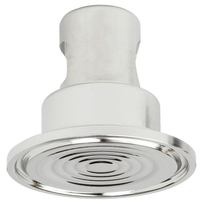
Diaphragm seal with sterile connection
Description
Diaphragm seals are used for the protection of pressure measuring instruments in applications with difficult media. In diaphragm seal systems, the diaphragm of the diaphragm seal effects the separation of the instrument and the medium. The pressure is transmitted to the measuring instrument via the system fill fluid which is inside the diaphragm seal system.
For the implementation of demanding customer applications, there are a wide variety of designs, materials and system fill fluids available.
For further technical information on diaphragm seals and diaphragm seal systems see IN 00.06 'Application, operating principle, designs'.
TRI-CLAMP ® is a trademark of the company Alfa Laval AB SE
For further approvals see page 7
Special features
- Quick cleaning, without residue
- Clamp connection easy to open for cleaning and seal replacement
- Suitable for SIP and CIP
- EHEDG-certified and 3-A marked
- Compliant per ASME BPE
| Model | 990.22 |
| Product family | 990 |
| Subcategory | Diaphragm seal with clamp connection (TRI-CLAMP) |
| Pressure ranges | 0…0.6 bar · 0…40 bar · 0…8.7 psi · 0…580 psi |
| Process connection | Clamp connection per DIN 32676Clamp connection per BS4825 Part 3Clamp connection per ISO 2852Pipe standard per DIN 11866 row B and ISO 1127 row 1Pipe standard per DIN 11866 row C or ASME BPEPipe standard per DIN 11866 row A and DIN 11850 row 2 |
| Process temperature | ≤ +400 °C |
| Case material | Stainless steel 1.4435 (316L), Hastelloy C22 (2.4602), Hastelloy C276 (2.4819) |
| Wetted parts material | Stainless steel 1.4435 (316L), Hastelloy C22 (2.4602), Hastelloy C276 (2.4819) |
| Certifications | 3-AEHEDGCRNFDA |
| Datasheet languages | EN |
| Models 990.22, 990.52 and 990.53 | Standard | Option |
|---|---|---|
| Pressure range | 0 ... 0.6 bar to 0 ... 40 bar [0 ... 8.7 psi to 0 ... 580 psi] ¹⁾ or all other equivalent vacuum or combined pressure and vacuum ranges | |
| Level of cleanliness of wetted parts | Oil and grease free per ASTM G93-03 level FWIKA standard (< 1,000 mg/m²) | ■ Oil and grease free per ASTM G93-03 level D and ISO 15001 (< 220 mg/m 2 ) ■ Oil and grease free per ASTM G93-03 level C and ISO 15001 (< 66 mg/m²) |
| Origin of wetted parts | International | ■ EU ■ CH ■ USA |
| Surface roughness of wetted parts | Ra ≤ 0.76 μm per ASME BPE SF3 (except for weld seam) | Ra ≤ 0.38 μm per ASME BPE SF4, only with electropolished surface (except for weld seam) |
| Connection to the measuring instrument | Axial adapter | Axial adapter with G1/2, G1/4, 1/2 NPT or 1/4 NPT (female) |
| Type of mounting | Direct mounting | ■ Capillary ■ Cooling element |
| Vacuum service (see IN 00.25) | Basic service | ■ Premium service ■ Advanced service |
| Marking of the diaphragm seal | - | Per valid 3-A standard |
| Instrument mounting bracket (only for capillary option) | - | ■ Form H per DIN 16281, 100 mm, aluminium, black ■ Form H per DIN 16281, 100 mm, stainless steel ■ Bracket for pipe mounting, for pipe Ø20 ... 80 mm, steel (see data sheet AC 09.07) |
| Upper body of diaphragm seal | Wetted parts | Maximum permissible process temperature ¹⁾ in °C [°F] |
|---|---|---|
| Stainless steel 1.4435 (316L) | Stainless steel 1.4435 (316L) | 400 [752] |
| Hastelloy C22 (2.4602) | Hastelloy C22 (2.4602) | |
| Hastelloy C276 (2.4819) | Hastelloy C276 (2.4819) |
| DN | PN ¹⁾ | Dimensions in mm[in] | |||
|---|---|---|---|---|---|
| For pipe outer ∅xwall thickness | Pipe inner∅ | D | Mb | ||
| 26.9 | 40 | 26.9 x 1.6 [1.059 x 0.063] | 23.7 [0.933] | 50.5 [1.988] | 22 [0.866] |
| 33.7 | 40 | 33.7 x 2 [1.327 x 0.079] | 29.7 [1.169] | 50.5 [1.988] | 25 [0.984] |
| 42.4 | 40 | 42.4 x 2 [1.669 x 0.079] | 38.4 [1.512] | 64 [2.52] | 32 [1.26] |
| 48.3 | 40 | 48.3 x 2 [1.902 x 0.079] | 44.3 [1.744] | 64 [2.52] | 40 [1.575] |
| 60.3 | 40 | 60.3 x 2 [2.374 x 0.079] | 56.3 [2.217] | 77.5 [3.051] | 52 [2.047] |
| 76.1 | 25 | 76.1 x 2 [2.996 x 0.079] | 72.1 [2.839] | 91 [3.583] | 72 [2.835] |
| DN | PN ¹⁾ | Dimensions in mm[in] | |||
|---|---|---|---|---|---|
| For pipe outer ∅xwall thickness | Pipe inner∅ | D | Mb | ||
| 1 " | 40 | 25.4 x 1.65 [1 x 0.065] | 22.1 [0.87] | 50.5 [1.988] | 22 [0.866] |
| 1½ " | 40 | 38.1 x 1.65 [1.5 x 0.065] | 34.8 [1.37] | 50.5 [1.988] | 32 [1.26] |
| 2 " | 40 | 50.8 x 1.65 [2 x 0.065] | 47.5 [1.87] | 64 [2.52] | 40 [1.575] |
| 2½ " | 40 | 63.5 x 1.65 [2.5 x 0.065] | 60.2 [2.37] | 77.5 [3.051] | 52 [2.047] |
| 3 " | 25 | 76.2 x 1.65 [3 x 0.065] | 72.9 [2.87] | 91 [3.583] | 72 [2.835] |
View all (9)
| DN | PN ¹⁾ | Dimensions in mm[in] | |||
|---|---|---|---|---|---|
| For pipe outer ∅xwall thickness | Pipe inner∅ | D | Mb | ||
| 25,4 | 40 | 25.4 x 1.6 [1 x 0.063] | 22.2 [0.874] | 50.5 [1.988] | 22 [0.866] |
| 38,1 | 40 | 38.1 x 1.6 [1.5 x 0.063] | 34.9 [1.374] | 50.5 [1.988] | 32 [1.26] |
| 50,8 | 40 | 50.8 x 1.6 [2 x 0.063] | 47.6 [1.874] | 64 [2.52] | 40 [1.575] |
| 63,5 | 40 | 63.5 x 1.6 [2.5 x 0.063] | 60.3 [2.374] | 77.5 [3.051] | 52 [2.047] |
| 76,2 | 25 | 76.2 x 1.6 [3 x 0.063] | 73 [2.874] | 91 [3.583] | 72 [2.835] |
| DN | PN ¹⁾ | Dimensions in mm[in] | |||
|---|---|---|---|---|---|
| For pipe outer ∅xwall thickness | Pipe inner∅ | D | Mb | ||
| 25 | 40 | 29 x 1.5 [x 0.059] | 26 [1.024] | 50.5 [1.988] | 25 [0.984] |
| 32 | 40 | 35 x 1.5 [x 0.059] | 32 [1.26] | 50.5 [1.988] | 29 [1.142] |
| 40 | 40 | 41 x 1.5 [x 0.059] | 38 [1.496] | 50.5 [1.988] | 32 [1.26] |
| 50 | 40 | 53 x 1.5 [x 0.059] | 50 [1.969] | 64 [2.52] | 40 [1.575] |
| 65 | 25 | 70 x 2 [x 0.079] | 66 [2.598] | 91 [3.583] | 60 [2.362] |
| 80 | 25 | 85 x 2 [x 0.079] | 81 [3.189] | 106 [4.173] | 72 [2.835] |
| 100 | 25 | 104 x 2 [x 0.079] | 100 [3.937] | 119 [4.685] | 90 [3.543] |
| DN | PN ¹⁾ | Dimensions in mm[in] | |||
|---|---|---|---|---|---|
| For pipe outer ∅xwall thickness | Pipe inner∅ | D | Mb | ||
| 25 | 40 | 25 x 1.2 [0.984 x 0.047] | 22.6 [0.89] | 50.5 [1.988] | 22 [0.866] |
| 33.7 | 40 | 33.7 x 1.2 [1.327 x 0.047] | 31.3 [1.232] | 50.5 [1.988] | 25 [0.984] |
| 38 | 40 | 38 x 1.2 [1.496 x 0.047] | 35.6 [1.402] | 50.5 [1.988] | 32 [1.26] |
| 40 | 40 | 40 x 1.2 [1.575 x 0.047] | 37.6 [1.48] | 64 [2.52] | 32 [1.26] |
| 51 | 40 | 51 x 1.2 [2.008 x 0.047] | 48.6 [1.913] | 64 [2.52] | 40 [1.575] |
| 63.5 | 40 | 63.5 x 1.6 [2.5 x 0.063] | 60.3 [2.374] | 77.5 [3.051] | 52 [2.047] |
| 70 | 25 | 70 x 1.6 [2.756 x 0.063] | 66.8 [2.63] | 91 [3.583] | 60 [2.362] |
| 76.1 | 25 | 76.1 x 1.6 [2.996 x 0.063] | 72.9 [2.87] | 91 [3.583] | 72 [2.835] |
| 88.9 | 25 | 88.9 x 2 [3.5 x 0.079] | 84.9 [3.343] | 106 [4.173] | 72 [2.835] |
| 101.6 | 25 | 101.6 x 2 [4 x 0.079] | 97.6 [3.843] | 119 [4.685] | 90 [3.543] |
| Logo | Description | Region |
|---|---|---|
| ® | 3-A Hygienic Design This instrument is 3-A marked, based on a third party verification for conformance to the 3-A standard. | USA |
| FEBRUARY 2026 TYPE EL CLASS I | EHEDG Hygienic Design | European Union |
| - | CRN Safety (e.g. electr. safety, overpressure, ...) | Canada |
| Certificates | ■ 2.2 test report per EN 10204 (e.g. state-of-the-art manufacturing, material proof, indica - tion accuracy for diaphragm seal systems) ■ 3.1 inspection certificate per EN 10204 (e.g. material proof for wetted metallic parts, indication accuracy for diaphragm seal systems) ■ FDA conformity of the system fill fluid ■ 3-A conformity of the diaphragm seal, based on a third party verification ■ EHEDG conformity ■ Manufacturer's declaration for food contact materials regarding regulation (EC) No. 1935/2004 ■ Others on request |
|---|
Couldn't find the answer in the documentation? An engineer will reply within a business day.
Ask an engineer →