
WIKA · Pressure measurement · Family 712
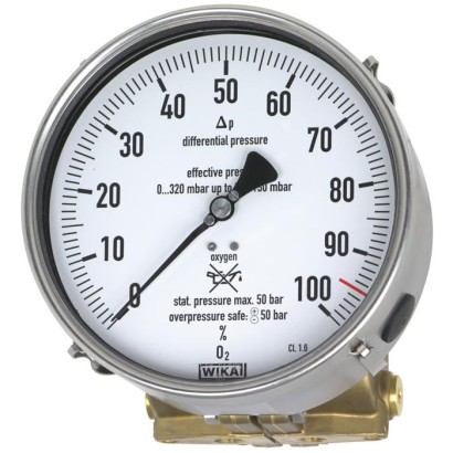
Differential pressure gauge
Cryo Gauge, copper alloy or stainless steel, NS 160
Range
0…4000 mbar
Output
4-20 mA · 4-20mA
Accuracy
2.5
Protection
IP65
CEEACRoHSREACHGOSTKazInMetrMTSCHSBelGIMUzstandardCPACRNBAMEx ia IIC T6/T5/T4 GbII 2G Ex ia IIC T6/T5/T4 GbATEX: II 2G Ex ia IIC T6/T5/T4IECEx: Ex ia IIC T6/T5/T4 Gb
Price
On request
Depends on configuration
Description
These high-quality differential pressure gauges are notable for their compact and robust design and are primarily used for level measurement on liquid gas tanks.
With 6 different measuring cells, all usual tank sizes in cryotechnology are covered. The large overlap in measuring ranges of the measuring cells enables the setting for gas types such as Ar, O 2 , N 2 or CO 2 over the entire scale with 270 angular degrees. The span adjustment is accessible from outside and does not affect the zero point.
for further approvals see page 4
Special features
- Differential pressure measuring ranges from 0 … 40 mbar to 0 ... 4,000 mbar
- High working pressure (static pressure) of 50 bar
- Overpressure safety either side up to 50 bar
- Scalable measuring ranges (maximum turndown of 1 : 3.5)
- Compact valve manifold with working pressure indication (optional)
Identification
| Model | 712.15.160 |
| Product family | 712 |
| Subcategory | Differential pressure gauge |
Measuring range
| Pressure ranges | 0…40 mbar · 0…140 mbar · 0…280 mbar · 0…560 mbar · 0…1130 mbar · 0…2300 mbar · 0…4000 mbar · 0…80 mbar · 0…160 mbar · 0…320 mbar · 0…650 mbar · 0…1150 mbar |
Accuracy
| Accuracy class | 2.5 |
| Accuracy standard | EN 837-1 |
Process conditions
| Process connection | 2 x G ¼, female, centre distance 37 mm2 x ¼ NPT, female, centre distance 37 mm2xG 1/4 female, centre distance 37 mm2 x 1/4 NPT female, centre distance 37 mmG 1/4 female, centre distance 37 mm1/4 NPT female, centre distance 37 mm |
| Process temperature | −40…+80 °C |
Electrical characteristics
| Output signal | 4-20 mA |
| Power supply | 12...30 V DC |
| Electrical connection | Cable socket PA 6, black |
| Switching function | Exceeds set point (index 1), breaks at set point (index 2), change-over contact (index 3) |
| Switching contacts | 1 |
Materials
| Case material | Stainless steel |
| Wetted parts material | Copper alloy CW614N (CuZn39Pb3), Stainless steel 316L, Stainless steel 1.4310, NBR, Stainless steel 1.4301, Stainless steel 1.4305 |
| Sealing material | NBR, PTFE |
Operating environment
| Ambient temperature | −40…+80 °C |
| IP rating | IP65 |
Certifications and approvals
| Certifications | CEEACRoHSREACHGOSTKazInMetrMTSCHSBelGIMUzstandardCPACRNBAM |
| Explosion protection | Ex ia IIC T6/T5/T4 GbII 2G Ex ia IIC T6/T5/T4 GbATEX: II 2G Ex ia IIC T6/T5/T4IECEx: Ex ia IIC T6/T5/T4 Gb |
Additional details
| Dial size | 160 mm |
| Datasheet languages | EN, DE |
Tables from datasheet
Models 712.15.160 and 732.15.160
| Nominal size inmm | 160 | |
|---|---|---|
| Accuracy class | 2.5 Option: ■ 1.6 ■ 1.0 | |
| Scale ranges | Measuring cell 140 mbar: Setting range 0 Measuring cell 280 mbar: Setting range 0 Measuring cell 560 mbar: Setting range 0 Measuring cell 1,130 mbar: Setting range 0 Measuring cell 2,300 mbar: Setting range 0 Measuring cell 4,000 mbar: Setting range 0 | …40mbar to 0 …140 mbar …80mbar to 0 …280 mbar …160 mbar to 0 …560 mbar …320 mbar to 0 …1,130 mbar …650 mbar to 0 …2,300 mbar …1,150 mbar to 0 …4,000 mbar |
| Scale | Single scale Option: Individual scale design | |
| Zero point setting | By means of adjustable pointer | |
| Overload safety and max. working pressure (static pressure) | Either side max. 50 bar | |
| Connection location | Lower mount (radial) | |
| Process connection | ■ 2xG ¼ , female, centre distance37mm ■ 2 x ¼ NPT, female, centre distance37mm others on request Option: Adapter for process connection, see page 6 | |
| Wetted materials | ||
| Measuring cell flanges | Model 712.15: Copper alloy CW614N (CuZn39Pb3) Model 732.15: Stainless steel 316L | |
| Compression spring | Stainless steel 1.4310 | |
| Separating diaphragm | NBR | |
| Transmission parts | Stainless steel 1.4301 and 1.4305 | |
| Non-wetted materials | ||
| Case | Stainless steel | |
| Bayonet ring | Stainless steel | |
| Movement | Stainless steel | |
| Dial | Aluminium, white | |
| Pointer | Adjustable pointer, black aluminium | |
| Window | Polycarbonate (PC) | |
| Ingress protection per IEC/EN 60529 | IP65 | |
| Mounting | According to affixed symbols ⊕high pressure, ⊖low pressure |
| Non-Ex version: Models 712.15.160 and 732.15.160 optionally with model 891.44 1) | Ex version: Models 712.15.160 and 732.15.160 with model 892.44 1) | |
|---|---|---|
| Ambient | -40 …+60 °C with oxygen -40 …+80 °C | -40 ...+60 °C for temperature class T6 and T5 -40 ...+80 °C for temperature class T4 |
| Medium | -40 …+60 °C with oxygen -40 …+80 °C | -40 …+60 °C with oxygen -40 ...+60 °C for temperature class T6 and T5 -40 ...+80 °C for temperature class T4 |
| Logo | Description | Country |
|---|---|---|
| EU declaration of conformity ■ EMCdirective ■ Pressure equipment directive ■ ATEX directive (option) 1) Hazardous areas - Ex ia Gas [II 2G Ex ia IIC T6/T5/T4 | European Union | |
| IECEx (option) 1) Hazardous areas - Ex ia Gas [Ex ia IIC T6/T5/T4 Gb] | International | |
| EAC (option) ■ EMCdirective ■ Pressure equipment directive ■ Low voltage directive ■ Hazardous areas 1) | Eurasian Economic Community | |
| GOST (option) Metrology, measurement technology | Russia | |
| KazInMetr (option) Metrology, measurement technology | Kazakhstan | |
| - | MTSCHS (option) Permission for commissioning | Kazakhstan |
| BelGIM (option) Metrology, measurement technology | Belarus | |
| Uzstandard (option) Metrology, measurement technology | Uzbekistan | |
| - | CPA Metrology, measurement technology | China |
| - | CRN Safety (e.g. electr. safety, overpressure, ...) | Canada |
| BAM Oxygen application | Germany |
Specifications
| Valves | 2 x shut-off valve, 1 x pressure compensating valve |
|---|---|
| Test connection | M20 x 1.5 with sealing cap (DIN 16287-A) |
| Valve body | ■ Copper alloy CW614N (CuZn39Pb3) for model 712.15 ■ Stainless steel 316L for model 732.15 |
| Spindle with conical nipple | ■ Copper alloy for model 712.15 ■ Stainless steel 316L for model 732.15 |
| Packing/sealing | NBR/PTFE With the valve fully-opened, the spindle area is isolated from the process by a metallic seal, the packing is not loaded and the spindle thread is not in contact with the measured media. |
| Working pressure indication | ■ Bourdon tube pressure gauge, copper alloy; model 212.20.100; see data sheet PM02.01 ■ Bourdon tube pressure gauge, stainless steel, model 232.50.100, see data sheet PM02.02 ■ Bourdon tube pressure gauge, stainless steel, safety version; model 232.30.100; see data sheet PM02.04 |
View all (6)
Specifications
| Material | ■ Copper alloy CW614N (CuZn39Pb3) for model 712.15 ■ Stainless steel 316L for model 732.15 |
|---|---|
| Process connections (wetted) | 2 x G¼, female, centre distance 31 mmor 54 mmor 2 x ¼NPT, female, centre distance31mmor54mm |
| Specifications | Models 891.44 and 892.44 (Ex version) | |
|---|---|---|
| Output signal | 4 …20mA, 2-wire | |
| Supply voltage U B | Non-Ex version, model 891.44:DC 12V < U B ≤ 30V Ex version, model 892.44:DC 14V < U B ≤ 30V | |
| Influence of supply voltage | ≤ 0.1 %of full scale/10V | |
| Permissible residual ripple | ≤ 10 %ss | |
| Permissible max. load R A | RA ≤ (U B - 12 V)/0.02 A with R A in Ωand U B in V, however max.600Ω | |
| Effect of load | ≤ 0.1 %of full scale | |
| Adjustability | ||
| Zero point, electrical | Adjustment of the zero point through brief bridging of terminals 5 and 6 or using the 'scale selection switch' option, selectable via button 1) | |
| Scale selection | 4 scales selectable via BCD switch | |
| Linear error | ≤ 1.0 %of span (terminal method) | |
| Compensated temperature range | -40 …+80 °C | |
| Temperature coefficients in the compensated temperature range | ||
| MeanTC zero point | ≤ 0.3 %of span/10 K | |
| MeanTC span | ≤ 0.3 %of span/10 K | |
| Electrical connection | Cable socket PA 6, black PerVDE 0110 insulation group C/250V Cable gland M20 x 1.5 Strain relief 6 screw terminals + PE for conductor cross-section | 2.5 mm² |
| Electrical safety | Protection against reverse polarity and overvoltage | |
| Ingress protection | IP65 per EN/IEC 60529 | |
| Safety-related maximum values for Ex version, model 892.44 | ||
| Supply voltage U i | DC 14 ...30V | |
| Short-circuit current I i | ≤ 100mA | |
| Power P i | ≤ 720mW | |
| Internal capacitance C i | ≤ 17.5 nF | |
| Internal inductance L i | negligible | |
| Designation of connection terminals, 2-wire | Do not use this | Terminals 3, 4, 5 and 6: For internal use only |
| terminal UB+/Sig | ||
| +0 V/Sig- | Connection must not be used for equipotential bonding.The instrument must be incorporated in the equipotential bonding via the process connection. |
Application areas not described yet
Describe your operating conditions — our engineer will suggest a model and use case.
Couldn't find the answer in the documentation? An engineer will reply within a business day.
Ask an engineer →