
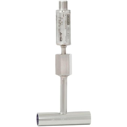
ترمومتر مقاومة مصغّر
الوصف
يوفر مقياس الحرارة المقاوم طراز TR21-B قياسًا لدرجة الحرارة في التطبيقات الصحية، ويمكن استخدامه لقياس الوسائط السائلة والغازية ضمن المجال من -30 ... +150 °C [-22 ... +302 °F]. وللاستخدام في المناطق الخطرة، تتوفر إصدارات ذات أمان جوهري.
نهايات التوصيل مصقولة ومجهزة للحام المداري. وتلبي وصلات العملية المتطلبات الصارمة، من حيث المواد والتصميم، لنقاط القياس الصحية. جميع المكونات الكهربائية محمية ضد الرطوبة (IP67 أو IP69K).
يتوفر مقياس الحرارة المقاوم بإخراج مباشر للمستشعر أو مع مرسل مدمج، ويمكن تهيئته بشكل فردي عبر برنامج إعداد WIKAsoft-TT PC. ويمكن ضبط مجال القياس، والتخميد، وإشارة الخطأ وفقًا لـ NAMUR NE 043 ورقم TAG.
للموافقات الإضافية، راجع الصفحة 5
طراز TR21-B مع هيكل تمرير خلالي
للمعايرة السهلة أو أعمال الصيانة، يمكن استبدال المستشعر دون الحاجة إلى فتح خط العملية. وبذلك يمكن تقليل مخاطر سوء النظافة وتقليل فترات التوقف.
يضمن التحميل بنابض، المدمج في صامولة الوصلة، التلامس بين رأس المستشعر وقاع أنبوب الحماية، وبالتالي يضمن زمن استجابة قصيرًا ودقة عالية مستمرة. ويمكن اختيار طول الإدخال ووصلة العملية والمستشعر وطريقة التوصيل لكل منها وفقًا للتطبيق المعني ضمن معلومات الطلب. يتم إجراء التوصيل الكهربائي عبر موصل دائري M12 x 1.
بالنسبة للتطبيقات التي تتطلب تعقيم الجهاز في الأوتوكلاف، تتوفر نسخة جهاز مقاومة بشكل خاص لدرجات الحرارة العالية.
المزايا
- إمكانية معايرة المستشعر دون الحاجة إلى فتح العملية
- توصيل كهربائي بسيط وسريع عبر قابس M12 x 1
- مع خرج حساس مباشر (Pt100/Pt1000 بنسخة توصيل ثلاثي أو رباعي الأسلاك) أو مرسل مدمج بإشارة خرج 4 ... 20 mA، قابل للمعايرة الفردية عبر برنامج التهيئة المجاني WIKAsoft-TT للحاسوب
- الأجزاء الملامسة للوسط من الفولاذ المقاوم للصدأ 1.4435
- ذو تصريف ذاتي ومساحة ميته مصغرة، خامات وجودات تشطيب السطح وفقاً لمعايير التصميم الصحي
الأسئلة والأجوبة
ما هو مجال قياس درجة الحرارة لهذا الطراز؟
يقيس TR21-B الوسائط السائلة والغازية ضمن المجال من -30 … +150 °C.
ما هي دقة القياس المتوفرة؟
دقة المرسل ±0.25 K، بينما يتوفر المستشعر بفئتي Class A وAA.
ما هي وصلات العملية المتاحة؟
يتوفر الطراز بوصلات للحام المداري أو بوصلة G3/8"، مع هيكل تمرير خلالي وأنبوب حماية من الفولاذ المقاوم للصدأ 1.4435 أو 316L.
هل يناسب هذا الجهاز التطبيقات الصحية والصيدلانية؟
نعم؛ فالأجزاء الملامسة للوسط من الفولاذ المقاوم للصدأ 1.4435، والتصميم ذاتي التصريف ومقلّل الفراغات الميتة، ويطابق مواد وتشطيب الأسطح معايير التصميم الصحي.
كيف يتم التوصيل الكهربائي؟
عبر موصل دائري M12 x 1 رباعي الأطراف، مع تغذية DC 10 ... 30V عند استخدام المرسل المدمج.
هل توجد نسخ للمناطق الخطرة؟
نعم، تتوفر إصدارات ذات أمان جوهري للاستخدام في المناطق الخطرة.
ما الذي يميز TR21-B عن غيره من مقاييس الحرارة المقاومة؟
يمكن استبدال المستشعر ومعايرته دون فتح خط العملية، مما يقلل مخاطر سوء النظافة وفترات التوقف، كما يضمن التحميل بنابض زمن استجابة قصيرًا ودقة عالية مستمرة.
ما هي الشهادات التي يحملها الجهاز؟
يحمل شهادات CE وEAC وRoHS وREACH، ودرجة حماية IP67 ضد الرطوبة.
| الطراز | TR21-B |
| السلسلة | TR21 |
| النوع الفرعي | Resistance thermometer |
| نطاق درجة الحرارة | −30…+150 °C · +0…+150 °C |
| فئة الدقة | ±0.25 K (transmitter), Class A (sensor) |
| وصلة العملية | Orbital weldingG3/8" |
| درجة حرارة العملية | −30…+150 °C |
| إشارة الخرج | 4-20mA · Direct sensor output |
| التغذية | DC 10 ... 30V |
| وصلة كهربائية | M12 x 1 circular connector (4-pin) |
| مادة المجس | Stainless steel 1.4435, Stainless steel 316L |
| مادة جراب الحرارة | Stainless steel 1.4435, Stainless steel 316L |
| حرارة المحيط | −50…+85 °C |
| تصنيف IP | IP67 |
| الشهادات | CEEACRoHSREACH |
| حماية الانفجار | Intrinsically safe versions available |
| نوع المستشعر | Pt100, Pt1000 |
| فئة المستشعر | AA, A |
| جراب الحرارة | نعم |
| شكل جراب الحرارة | flow-through housing |
| لغات ورقة البيانات | EN, DE |
| Type of measuring element | ||
|---|---|---|
| 4 ... 20 mAversion (models TR21-B-xTT, TR21-B-xTB) | ■ Pt1000 (measuring current < 0.3 mA;self-heating can be ignored) ■ Face-sensitive Pt1000 1) (measuring current < 0.3 mA;self-heating can be ignored) | |
| Pt100 (model TR21-B-xPx)/Pt1000 (model TR21-B-xRx) version | ■ Pt100 (measuring current: 0.1 ... 1.0 mA) ■ Face-sensitive Pt100 (measuring current 0.1 ... 1.0 mA) 1) ■ Pt1000 (measuring current: 0.1 ... 0.3 mA) ■ Face-sensitive Pt1000 (measuring current 0.1 ... 0.3 mA) 1) | |
| → For detailed specifications for Pt sensors, see Technical information IN 00.17 at www.wika.com. | ||
| Connection method | ||
| 4 ... 20 mAversion (models TR21-B-xTT, TR21-B-xTB) | 2-wire | |
| Pt100 (model TR21-B-xPx)/Pt1000 (model TR21-B-xRx) version | 3-wire | With a cable length of 30 mor longer, measuring deviations can occur |
| 4-wire | The lead resistance can be ignored | |
| Tolerance value of the measuring element 2) per IEC 60751 | ||
| 4 ... 20 mAversion (models TR21-B-xTT, TR21-B-xTB) | Class A | |
| Pt100 (model TR21-B-xPx)/Pt1000 (model TR21-B-xRx) version | ■ Class AA ■ Class A | 3) |
| Tolerance value of the measuring element 2) per IEC 60751 | Class A |
|---|---|
| Measuring deviation of the transmitter per IEC 62828 | ±0.25 K |
| Total measuring deviation in accordance with IEC 62828 | Measuring deviation of the measuring element + transmitter |
| Influence of the ambient temperature | 0.1 %of span / 10 KT a |
| Influence of supply voltage | ±0.025 %/V(depending on the supply voltage U B ) |
| Influence of the load | ±0.05 %/ 100Ω |
| Linearisation | Linear to temperature per IEC 60751 |
| Linearisation error | ±0.1% 1) of the set measuring span |
| Reference conditions | |
| Ambient temperatureT a ref | 23 °C |
| Supply voltage U B ref | DC 12V |
| Temperature range | ||
|---|---|---|
| 4 ...20 mAversion (modelsTR21-B-xTT,TR21-B-xTB) | -30 ...+150 °C [-22 ...+302 °F] 1) | |
| Pt100 (model TR21-B-xPx)/ | Class AA | 0 ... 150 °C [32 ... 302 °F] |
| Pt1000 (model TR21-B-xRx) version | Class A -30 ...+150 °C [-22 Configurable °C, °F, K | ...+302 |
| Temperature at the connector (Pt100, Pt1000 version) | Max. 85 °C [185 °F] | |
| Measuring span (4 ... 20 mA version) | Minimum 20 K, maximum 300 K |
| Type of process connection | ■ Flow-through housing ■ Angular housing | |
|---|---|---|
| Protection tube | ||
| Protection tube model | TW61 | |
| Protection tube design | → see drawings from page 10 | |
| Surface roughness | Per DIN 11866 row A, B | ■ R a < 0.8 μm ■ R a < 0.4 μm electropolished |
| Per DIN 11866 row C, ASME-BPE | ■ R a < 0.76 μm ■ R a < 0.38 μm electropolished | |
| Connection to thermometer | G3/8" | |
| Material (wetted) | Per DIN 11866 row A, B | Stainless steel 1.4435 |
| Per DIN 11866 row C, ASME-BPE | Stainless steel 316L |
عرض الكل (20)
| Analogue output | 4 ... 20 mA, 2-wire |
|---|---|
| Load R A | R A ≤ (U B - 10 V) / 23 mAwith R A in Ωand U B inV |
| The permissible load depends on the loop supply voltage. For communication with the instrument with programming unit PU-548, a max. load of 350 Ωis admissible. | |
| Load diagram | Load R A inΩ Voltage U B inV 0 10 24 30 36 1083 833 583 Not for instruments with Ex version |
| Factory configuration | |
|---|---|
| Measuring range | Measuring range 0 ... 150 °C [32 ... 302 °F] Other measuring ranges are adjustable |
| Current signals for error signalling | Configurable in accordance with NAMUR NE 043 downscale ≤ 3.6mA upscale ≥ 21.0mA |
| Current value for sensor short-circuit | Not configurable in accordance with NAMUR NE 043 downscale ≤ 3.6mA |
| Communication | |
| Info data | TAG no., description and user message can be stored in transmitter |
| Configuration and calibration data | Permanently stored |
| Configuration software | WIKAsoft-TT → Configuration software (multilingual) as a download from www.wika.com |
| Voltage supply | |
| Supply voltage U B | DC 10 ...30V |
| Supply voltage input | Protected against reverse polarity |
| Permissible residual ripple of supply voltage | 10 %generated by U B < 3 %ripple of the output current |
| Time response | |
| Switch-on delay, electrical | Max. 4 s (time before the first measured value) |
| Warm-up time | After approx. 4 minutes, the instrument will function to the specifications (accuracy) given in the data sheet. |
| Response time (per IEC 60751) | t 50 < 3.2 s t 90 < 7.3 s |
| Connection type | M12 x 1 circular connector (4-pin) |
|---|---|
| Material | Stainless steel 1.4404 |
| Pin | Signal | Description |
|---|---|---|
| 1 | L+ | 10 ...30V |
| 2 | VQ | not connected |
| 3 | L- | 0V |
| 4 | C | not connected |
| Operating conditions | |
|---|---|
| Ambient temperature range | |
| 4 ... 20 mAversion (models TR21-B-xTT, TR21-B-xTB) | -40 ...+85 °C [-40 ...+185 °F] |
| Pt100 (model TR21-B-xPx)/Pt1000 (model TR21-B-xRx) version | -50 ...+85 °C [-58 ...+185 °F] -40 ...+85 °C [-40 ...+185 °F] |
| Climate class per IEC 60654-1 | |
| 4 ... 20 mAversion (models TR21-B-xTT, TR21-B-xTB) | Cx (-40 ...+85 °C [-40 ...+185 °F], 5 ... 95 %r.h.) |
| Pt100 (model TR21-B-xPx)/Pt1000 (model TR21-B-xRx) version | Cx (-50 ...+85 °C [-58 ...+185 °F], 5 ... 95 %r.h.) 100 %r.h., condensation allowed |
| Max. operating pressure | Dependent on particular process connection |
| Salt fog | IEC 60068-2-11 |
| Shock resistance per IEC 60068-2-27 | 50 g, 6 ms, 3 axes, 3 directions, three times per direction |
| Maximum permissible autoclaving conditions | Max. 134 °C, 3 bar abs., 100 %r.h., duration 20 min., max. 50 cycles |
| Autoclavable with mounted protective cap at coupler connector | |
| Conditions for outdoor use (only applies to UL approval) | ■ The instrument is suitable for applications with pollution degree 3. ■ The power supply must be suitable for operation above 2,000m should the temperature transmitter be used at this altitude. ■ The instrument shall be installed in locations sheltered from the weather. ■ The instrument shall be installed sun/UV irradiation protected. |
| Ingress protection (IP code) | |
| Case with connected connector 1) | ■ IP67 per IEC/EN 60529 ■ IP69 per IEC/EN 60529 ■ IP69K per ISO 20653 |
| The stated ingress protection only applies when plugged in using line connectors that have the appropriate ingress protection. | |
| Coupler connector, not connected | IP67 per IEC/EN 60529 |
| Weight in kg | approx. 0.3 ... 2.5 (depending on version) |
| Logo | Description | Region |
|---|---|---|
| EU declaration of conformity | European Union | |
| EMCdirective 1) 2) EN 61326 emission (group 1, class B) and immunity (industrial application) | ||
| Pressure equipment directive For thermowells/protection tubes > DN 25 (1") and for the associated marking on the measuring instrument or thermowell/protection tube,WIKA confirms conformity with the pressure equipment directive in accordance with the conformity assessment procedure, module H. thermowells/protection tubes with nominal widths of ≤ DN 25 (1"), a CE marking in with the pressure equipment directive (PED) is not permitted and therefore, they are engineering | ||
| For accordance designed and manufactured without CE marking in line with the applicable sound practice. RoHS directive | ||
| UL - only for instrument version without explosion protection Safety (e.g. electr. safety, overpressure, ...) | USA and Canada |
| Logo | Description | Region | |
|---|---|---|---|
| EU declaration of conformity | European Union | ||
| ATEX directive Hazardous areas | |||
| IECEx - in combination with ATEX Hazardous areas Zone 0 gas Ex ia IIC T1 ...T6 Ga Zone 1 mounting to zone 0 gas Ex ia IIC T1 ...T6 Ga/Gb Zone 1 gas Ex ia IIC T1 ...T6 Gb Zone 20 dust Ex ia IIIC T135 °C Da Zone 21 mounting to zone 20 dust Ex ia IIIC T135 °C Da/Db | International | ||
| CSA Safety (e.g. electr. safety, overpressure, ...) Hazardous areas Class I, division 1 or 2, groups A, B, C, DT1 ...T6 Class I, zone 0 or 1, IIC Ex/AEx ia IIC T1 ...T6 Ga Class II / III, division 1 or 2, groups E, F, GT1 ...T6 / 135 °C | USA and Canada | ||
| EAC 1) | Eurasian Economic Community | ||
| Hazardous areas Zone 0 gas 0Ex ia IICT6…T1GaX Zone 1 gas 1Ex ia IICT6…T1GbX Zone 1 gas Ex ia IIIC T135 °C Gb X Zone 1 mounting to zone 0 gas Ex ia IIC T6 …T1Ga/Gb X Zone 20 dust Ex ia IIIC T135 °C Da X Zone 20 dust Ex ia IIIC T80 …T440 Da X Zone 21 dust Ex ia IIIC T80 …T440 Db X | |||
| Ex Ukraine Hazardous areas Zone 0 gas Zone 20 dust Zone 1 mounting to zone 0 gas Zone 21 mounting to zone 20 dust Zone 1 gas Zone 21 dust Zone 1 gas | II 1G Ex ia IICT6…T1Ga II 1D Ex ia IIIC T135 °C Da II 1/2G Ex ia IIC T6 …T1Ga/Gb II 1/2D Ex ia IIIC T135 °C Da/Db II 2G Ex ia IICT6…T1Gb II 2D Ex ia IIIC T135 °C Db II 2G Ex ib IICT6…T1Gb | Ukraine | |
| CCC 3) Hazardous areas Zone 0 gas Ex ia IIC T1~T6 Ga Zone 1 gas Ex ia IIC T1~T6 Gb Zone 1 mounting to zone 0 gas Ex ia IIC T1~T6 Ga/Gb | China | ||
| PAC Russia Metrology, measurement technology | Russia | ||
| PAC Kazakhstan Metrology, measurement technology | Kazakhstan |
| Logo | Description | Region |
|---|---|---|
| - | MChS Permission for commissioning | Kazakhstan |
| PAC Belarus Metrology, measurement technology | Belarus | |
| PAC Uzbekistan Metrology, measurement technology | Uzbekistan | |
| ® | 3-A 4) Hygienic Design | USA |
| JANUARY 2019 TYPE EL CLASS I | EHEDG 4) Hygienic Design | European Union |
| Certificates | ■ 2.2 test report ■ 3.1 inspection certificate ■ DAkkS calibration certificate ■ Manufacturer's declaration regarding regulation (EC) 1935/2004 and (EC) 2023/2006 ■ Certificate of the surface roughness of wetted parts | |
|---|---|---|
| Hygienic certificates | 3-A approval | EHEDG approval |
| Flow-through housing | For all dimensions | For all dimensions |
| Angular housing | DIN 11866 row A:DN 32 ... 100 DIN 11866 row B:DN 25 ... 80 DIN 11866 row C:DN 1 ½" ... 4" | DIN 11866 row A:DN 32 ... 100 DIN 11866 row B:DN 25 ... 80 DIN 11866 row C:DN 1 ½" ... 4" |
| Patent number | Description |
|---|---|
| DE 102010037994 US 12 897.080 | Dead-space free welding nipple for protection tube modelTW61 |
| Hazardous gas atmosphere | Temperature class | Ambient temperature range (T a ) | Maximum surface temperature (T max ) at the tip of the probe or protection tube |
|---|---|---|---|
| II 1G Ex ia IIC T1 - T6 Ga II 1/2G Ex ia IIC T1 - T6 Ga/Gb II 2G Ex ia IIC T1 - T6 Gb | T6 | -40 ...+45 °C | T M (medium temperature) + self-heating (15 K) Pay attention to the special conditions for safe |
| T5 | -40 ...+60 °C | use. | |
| T4 | -40 ...+85 °C | ||
| T3 | -40 ...+85 °C | ||
| T2 | -40 ...+85 °C | ||
| T1 | -40 ...+85 °C |
| Hazardous dust atmosphere | Power P i | Ambient temperature range (T a ) | Maximum surface temperature (T max ) at the tip of the probe or protection tube |
|---|---|---|---|
| II 1D Ex ia IIIC T135 °C Da II 1/2D Ex ia IIIC T135 °C Da/Db II 2D Ex ia IIIC T135 °C Db | 750mW 650mW 550mW | -40 ...+40 °C -40 ...+70 °C -40 ...+85 °C | T M (medium temperature) + self-heating (15 K) Pay attention to the special conditions for safe use. |
| Parameters | Hazardous gas atmosphere | Hazardous dust atmosphere |
|---|---|---|
| Terminals | + / - | + / - |
| Voltage U i | DC 30V | DC 30V |
| Current l i | 120mA | 120mA |
| Power P i | 800mW | 750/650/550mW |
| Effective internal capacitance C i | 29.7 nF | 29.7 nF |
| Effective internal inductance L i | Negligible | Negligible |
| Maximum self-heating at the probe or protection tube tip | 15 K | 15 K |
| Marking | Temperature class | Ambient temperature range (T a ) | Maximum surface temperature (T max ) at the tip of the probe or protection tube |
|---|---|---|---|
| II 1G Ex ia IIC T1 - T6 Ga II 1/2G Ex ia IIC T1 - T6 Ga/Gb II 2G Ex ia IIC T1 - T6 Gb | T6 | -50 ...+80 °C | T M (medium temperature) + self-heating Pay attention to the special conditions for safe |
| T5 | -50 ...+85 °C | use. | |
| T4 | -50 ...+85 °C | ||
| T3 | -50 ...+85 °C | ||
| T2 | -50 ...+85 °C | ||
| T1 | -50 ...+85 °C |
| Marking | Power P i | Ambient temperature range (T a ) | Maximum surface temperature (T max ) at the tip of the probe or protection tube |
|---|---|---|---|
| II 1D Ex ia IIICT135 °C Da II 1/2D Ex ia IIICT135 °C Da/Db II 2D Ex ia IIICT135 °C Db | 750mW 650mW 550mW | -50 ...+40 °C -50 ...+70 °C -50 ...+85 °C | T M (medium temperature) + self-heating Pay attention to the special conditions for safe use. |
| Parameters | Gas applications | Dust applications |
|---|---|---|
| Terminals | 1 - 4 | 1 - 4 |
| Voltage U i | DC 30V | DC 30V |
| Current l i | 550mA | 250mA |
| Power P i | 1,500mW | 750/650/550mW |
| Effective internal capacitance C i | Negligible | Negligible |
| Effective internal inductance L i | Negligible | Negligible |
| Maximum self-heating at the probe or protection tube tip | (R th ) = 335 K/W | (R th ) = 335 K/W |
لم تجد الإجابة في الوثائق؟ سيرد المهندس خلال يوم عمل.
اسأل المهندس →28 مادة قياسية من عائلة TR21
إذا كنت تعرف الرمز — اختر مباشرة. إذا لا — استخدم المُهيِّئ في الوضع «01».