
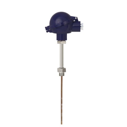
ترمومتر مقاومة
الوصف
يمكن دمج موازين الحرارة المقاومة في سلسلة الطراز هذه مع عدد كبير من تصاميم غلاف المسبار / أنبوب الحماية. يُوصى فقط في تطبيقات معيّنة بالعمل دون غلاف المسبار / أنبوب الحماية.
تتوفر مجموعة واسعة من التركيبات الممكنة لعنصر قياس Pt100 أو Pt1000، ورأس التوصيل، وطول الإدخال، وطول الرقبة، والتوصيل بغلاف المسبار / أنبوب الحماية، إلخ. وتُعد هذه الموازين مناسبة لأي بُعد لغلاف المسبار وأي تطبيق.
للموافقات الإضافية، راجع الصفحة 19
الشكل يسارًا: طراز TR10-B مع رأس توصيل BSZ الشكل في الوسط: طراز TR10-B مع رأس توصيل 1/4000
الشكل يمينًا: طراز TR10-B مع رأس توصيل PIH-L
يتوفر عدد كبير من الموافقات المختلفة للحماية من الانفجار الخاصة بـ TR10-B.
يمكن تركيب مرسلات WIKA تماثلية أو رقمية في رأس التوصيل الخاص بـ TR10-B.
المزايا
- مدى المستشعر من -196 ... +600 °C [-320 ... +1,112 °F]
- للتركيب في جميع تصميمات الجراب الواقي للحرارة القياسية
- عنصر قياس مزود بنابض ضغط (قابل للاستبدال)
- مستشعرات Pt100 أو Pt1000
- تتوفر نسخ مقاومة للانفجار لعدة أنواع من الموافقات
الأسئلة والأجوبة
ما هو نطاق القياس لمقياس الحرارة TR10-B؟
حسب تصميم الحساس، تغطي النطاقات المتاحة ما بين -196 … +600 °C، ومنها على سبيل المثال -50 … +500 °C و-30 … +300 °C و0 … +150 °C.
ما هي دقة القياس؟
الدقة هي ± (0.30 + 0.0050 |t|) °C لحساس من الفئة B.
هل يمكن تركيب الجهاز بدون غلاف حراري؟
الطراز TR10-B مصمم أساسًا للتركيب داخل غلاف حراري إضافي، وهو مناسب لجميع تصاميم الأغلفة القياسية؛ ولا يُوصى بالعمل بدونه إلا في تطبيقات محددة.
ما هي وصلة العملية المتوفرة؟
التوصيلات المتاحة تشمل M24 x 1.5 وM20 x 1.5 و½ NPT و¾ NPT.
ما هي الموافقات المتعلقة بالمناطق الخطرة؟
يتوفر الطراز بموافقات ATEX وIECEx وEACEx وCCC وINMETRO وNEPSI وKCs وPESO وEx Ukraine، مع نسخ Ex i للغاز (مناطق 0، 1، 2) وللغبار (مناطق 20، 21، 22)، وEx e وEx nA للغاز وEx t للغبار.
ما هو مستوى السلامة الوظيفية؟
الطراز مؤهل حتى مستوى SIL 2.
ما الذي يميز TR10-B عن الطرازات المجاورة؟
إدخال القياس المثبّت بنابض قابل للاستبدال يسمح بتغيير الحساس دون فك الغلاف الحراري، كما يمكن تركيب مرسلات WIKA تماثلية أو رقمية في رأس التوصيل.
ما هي درجة حرارة التشغيل المحيطية المسموحة؟
درجة حرارة البيئة المحيطة المسموحة هي -40 … +80 °C، وحماية الدخول IP65.
اجمع TR10-B لمهمتك
يُبنى رقم المادة تلقائيًا. عند الشك — تواصل مع مهندس؛ سنساعدك حسب معطيات الخط.
- اعتماد كهربائيWithout
- نوع الحماية من الاشتعالWithout
- المنطقةWithout
- مستشعر1xPt100, 3-wire
- فئة دقة المستشعرClass B, IEC 60751
- نطاق درجة الحرارة للفئة المحددة-50...+250°C
- الغطاء / الهيكلBSZ, Aluminum, ball shaped, flip-top
- دخول الكابلStandard cable gland for für A-/B-/J- heads
- حجم مقاس الخيط لمدخل الكابلM20 x 1.5
- مرسلWithout (terminal block)
- تفاصيل جهاز الإرسالWithout
- التوصيل بأنبوب الرقبةM24 x 1,5
- أنبوب الرقبةD = 12 x 2.5 mm
- حجم الخيطG 1/2 B
- مادة أنبوب الرقبةStainless steel
- طول الرقبة [MH/N]150
- طول الإدخال [A]100
- قطعة إدخال لقياس القطر—
- مُقاس/عنصر القياس داخل الغلاف (Sheath)Stainless steel 1.4571
- المتطلبات الميكانيكيةWithout
- الشهاداتWithout
أكمل التهيئة
اختر جميع الخيارات لإرسال الطلب.
| الطراز | TR10-B |
| السلسلة | TR10 |
| النوع الفرعي | Resistance thermometer |
| نطاق درجة الحرارة | −196…+600 °C · −196…+450 °C · −50…+500 °C · −50…+250 °C · −30…+300 °C · +0…+150 °C · −100…+450 °C |
| فئة الدقة | ± (0.30 + 0.0050 |t|) °C |
| مستوى السلامة الوظيفية (SIL) | SIL 2 |
| وصلة العملية | M24 x 1.5½ NPTM20 x 1.5¾NPT |
| درجة حرارة العملية | −196…+600 °C |
| إشارة الخرج | 4-20mA |
| وصلة كهربائية | Spring-loaded terminal block |
| مادة المجس | 1.4571, 316L |
| حرارة المحيط | −40…+80 °C |
| تصنيف IP | IP65 |
| الشهادات | CERoHSREACHEACNAMUR NE 024DNV GL |
| حماية الانفجار | Ex i (gas) Zone 0, 1, 2Ex i (dust) Zone 20, 21, 22Ex e (gas) Zone 1, 2Ex t (dust) Zone 21, 22Ex nA (gas) Zone 2ATEXIECExEACExCCCINMETRONEPSIKCsPESOEx UkraineATEX: II 1/2G Ex ia IIC T3...T6 Ga/Gb, II 1/2D Ex ia IIIC T65°C Da/DbIECEx: Ex ia IIC T3...T6 Ga/Gb, Ex ia IIIC T65°C Da/DbEACEx: Ex ia IIC T6...T1 Ga X, Ex ia IIC T6...T1 Gb X, Ex ia IIC T80...T440°C Da X, Ex ia IIC T80...T440°C Db X, Ex eb IIC T6...T1 Gb X, Ex ec IIC T6...T1 Gc X, Ex nA IIC T6...T1 Gc X, Ex tb IIC T85°C Db X, Ex tc IIC T85°C DcCCC: Ex ia IIC T3...T6 Ga, Ex ia IIC T3...T6 Ga/Gb, Ex ia IIC T125...T65°C Da, Ex ia IIC T125...T65°C Da/DbNEPSI: Ex ia IIC T1...T6 Ga, Ex ia IIC T1...T6 Gb, Ex ec IIC T1...T6 Gc, Ex tb IIC T135°C Db, Ex tc IIC T135°C DcKCs: Ex ia IIC T1~T6 Ga, Ex ia IIC T1~T6 Gb, Ex ia IIC T1~T6 Ga/Gb, Ex ia D20 T65/T95/T125°C, Ex ia D21 T65/T95/T125°CINMETRO: Ex ia IIC T3...T6 Ga, Ex ia IIC T3...T6 Ga/Gb, Ex ia IIC T125...T65°C Da, Ex ia IIC T125...T65°C Da/DbEx Ukraine: Ex ia IIC T3...T6 Ga, Ex ia IIC T3...T6 Ga/Gb, Ex ia IIC T125...T65°C Da, Ex ia IIC T125...T65°C Da/DbPESO: Ex ia IIC T3...T6 Ga, Ex ia IIC T3...T6 Ga/Gb, Ex ia IIC T125...T65°C Da, Ex ia IIC T125...T65°C Da/Db |
| نوع المستشعر | Pt100 |
| فئة المستشعر | B |
| قطر المجس | 3 mm |
| جراب الحرارة | نعم |
| لغات ورقة البيانات | EN, DE |
| Approval | Explosion protection | ||||
|---|---|---|---|---|---|
| Ex i (gas) Zone 0, 1, 2 | Ex i (dust) Zone 20, 21, 22 | Ex e (gas) Zone 1, 2 | Ex t (dust) Zone 21, 22 | Ex nA (gas) Zone 2 | |
| ATEX | x | x | x | x | x |
| IECEx | x | x | x | x | x |
| ECASEx | - | - | x | x | x |
| EACEx | x | x | x | x | x |
| Ex Ukraine | x | x | - | - | - |
| INMETRO | x | x | - | - | - |
| CCC | x | x | x | x | - |
| NEPSI | x | x | - | - | - |
| KCs | x | - | - | - | - |
| PESO | x | - | - | - | - |
| Model | Material | Thread size of cable inlet | Ingress pro- tection (max.) 1) 2) IEC/EN 60529 | Cap | Surface | Connection to neck tube | |
|---|---|---|---|---|---|---|---|
| BSZ, BSZ-K | BSZ | Aluminium | ■ M20 x 1.5 ■ ½NPT | IP65 | Spherical hinged cov- er with cylinder head screw | Blue, painted (RAL 5022) | ■ M24 x 1.5 ■ ½NPT |
| BSZ-H, BSZ-HK BSZ-K | BSS Plastic | BSS-H ■ M20 x 1.5 ■ ½NPT | BVS IP65 | BVS (NuG) Spherical hinged cov- er with cylinder head screw | 1/4000 Black | 5/6000 M24 x 1.5 | |
| BSZ-H, BSZ-HK | BSZ-H | Aluminium | ■ M20 x 1.5 ■ ½NPT | IP65 | Raised hinged cover with cylinder head screw | Blue, painted (RAL 5022) | ■ M24 x 1.5 ■ ½NPT |
| BSS BSZ-H (2 x cable outlet) | BSS-H Aluminium | BVS ■ 2 x M20 x 1.5 ■ 2x½NPT | BVS (NuG) IP65 | 5/6000 1/4000 Raised hinged cover with cylinder head screw | 7/8000 Blue, painted (RAL 5022) | 7/8000 DIH50 M24 x 1.5 | |
| BSZ-H / DIH10 3) | Aluminium | ■ M20 x 1.5 ■ ½NPT | IP65 | Raised hinged cover with cylinder head screw | Blue, painted (RAL 5022) | ■ M24 x 1.5 ■ ½NPT | |
| BSZ-H /TND 4) | Aluminium | ■ M20 x 1.5 ■ ½NPT | IP65 | Raised hinged cover with cylinder head screw | Blue, painted (RAL 5022) | ■ M24 x 1.5 ■ ½NPT | |
| BSZ-HK | Plastic | ■ M20 x 1.5 ■ ½NPT | IP65 | Raised hinged cover with cylinder head screw | Black | M24 x 1.5 | |
| BS | Aluminium | ■ M20 x 1.5 ■ ½NPT | IP65 | Flat cover with 2 screws | Blue, painted (RAL 5022) | ■ M24 x 1.5 ■ ½NPT | |
| BS | BSZ, BSZ-K BSS | BSZ-H, BSZ-HK Aluminium | BSS ■ M20 x 1.5 ■ ½NPT | BSS-H IP65 | BVS Spherical hinged cover with clamping lever | BVS (NuG) Blue, painted (RAL 5022) | 1/4000 ■ M24 x 1.5 ■ ½NPT |
| BSS | BSS-H BSS-H | BVS Aluminium | BVS (NuG) ■ M20 x 1.5 ■ ½NPT | 5/6000 1/4000 IP65 | 7/8000 Raised hinged cover with clamping lever | 7/8000 DIH50 andere Blue, painted (RAL 5022) | Anschlussgehäuse ■ M24 x 1.5 ■ ½NPT |
| BSS-H | BVS BVS | BVS (NuG) Stainless steel | 1/4000 M20 x 1.5 | 5/6000 IP65 | 7/8000 DIH50 7/8000 Precision-cast screw- on lid | andere Anschlussgehäuse Natural finish, electropo- lished | KN4-P M24 x 1.5 |
| Model | Explosion protection | |||||
|---|---|---|---|---|---|---|
| Without | Ex i (gas) Zone 0, 1, 2 | Ex i (dust) Zone 20, 21, 22 | Ex e (gas) Zone 1, 2 | Ex t (dust) Zone 21, 22 | Ex nA (gas) Zone 2 | |
| BSZ | x | x | x | x 1) | x 1) | x 2) |
| BSZ-K | x | x | - | - | - | - |
| BSZ-H | x | x | x | x 1) | x 1) | x 2) |
| BSZ-H (2 x cable outlet) | x | x | x | x 1) | x 1) | x 2) |
| BSZ-H / DIH10 3) | x | x | - | - | - | - |
| BSZ-H /TND 4) | x | x | - | - | - | - |
| BSZ-HK | x | x | - | - | - | - |
| BS | x | x | x | - | - | - |
| BSS | x | x | - | - | - | - |
| BSS-H | x | x | - | - | - | - |
| BVS | x | x | - | - | - | - |
| Model | Material | Thread size of cable inlet | Ingress protection (max.) 1) 2) IEC/EN 60529 | Cap | Surface | Connection to neck tube | |
|---|---|---|---|---|---|---|---|
| KN4-P | KN4-A | Aluminium | ■ ½NPT ■ M20 x 1.5 | IP65 | Screw-on lid | Blue, painted (RAL 5022) | ■ M24 x 1.5 ■ ½NPT |
| KN4-P 3) | Polypropylene | ½NPT | IP65 | Screw-on lid | White | ½NPT | |
| 1/4000 | BVC 1/4000 | Aluminium | ■ ½NPT ■ ¾NPT ■ M20 x 1.5 | IP66 | Screw-on lid | Blue, painted (RAL 5022) | ½NPT |
| 5/6000 1/4000 | 7/8000 Stainless steel | 7/8000 DIH50 andere ■ ½NPT ■ ¾NPT ■ M20 x 1.5 | KN4-P Anschlussgehäuse IP66 | BVC Screw-on lid | Natural finish | ½NPT | |
| 7/8000 | 7/8000 | Aluminium | ■ ½NPT ■ ¾NPT ■ M20 x 1.5 | IP66 | Screw-on lid | Blue, painted (RAL 5022) | ½NPT |
| 7/8000 DIH50 7/8000 | andere Anschlussgehäuse Stainless steel | KN4-P BVC ■ ½NPT ■ ¾NPT ■ M20 x 1.5 | IP66 | Screw-on lid | Natural finish | ½NPT | |
| 7/8000 DIH50 | 7/8000 / DIH50 4) | Aluminium | ■ ½NPT ■ ¾NPT ■ M20 x 1.5 | IP66 | Screw-on lid | Blue, painted (RAL 5022) | ½NPT |
| andere Anschlussgehäuse 7/8000 / DIH50 4) | KN4-P Stainless steel | BVC ■ ½NPT ■ ¾NPT ■ M20 x 1.5 | IP66 | Screw-on lid | Natural finish | ½NPT | |
| PIH-L | Aluminium | ■ ½NPT/ closed ■ M20 x 1.5 / closed ■ 2x½NPT ■ 2 x M20 x 1.5 | IP66 | Screw-on lid, flat | Blue upper body, painted (RAL 5022) | ■ ½NPT ■ M20 x 1.5 | |
| Grey lower body, painted (RAL 7032) | |||||||
| PIH-H | Aluminium | ■ ½NPT ■ M20 x 1.5 ■ 2x½NPT ■ 2 x M20 x 1.5 | IP66 | Screw-on lid, high | Blue upper body, painted (RAL 5022) | ■ ½NPT ■ M20 x 1.5 | |
| Grey lower body, painted (RAL 7032) | |||||||
| PIH-W / TND 5) | Aluminium | ■ ½NPT ■ M20 x 1.5 ■ 2x½NPT ■ 2 x M20 x 1.5 | IP66 | Screw-on lid, high | Blue upper body, painted (RAL 5022) Grey lower painted | ■ ½NPT ■ M20 x 1.5 | |
| body, (RAL 7032) |
عرض الكل (20)
| Model | Explosion protection | |||||
|---|---|---|---|---|---|---|
| Without | Ex i (gas) Zone 0, 1, 2 | Ex i (dust) Zone 20, 21, 22 | Ex e (gas) Zone 1, 2 | Ex t (dust) Zone 21, 22 | Ex nA (gas) Zone 2 | |
| KN4-A | x | x | - | - | - | - |
| KN4-P 1) | x | - | - | - | - | - |
| 1/4000 | x | x | x | x | x | x |
| 7/8000 | x | x | x | x | x | x |
| 7/8000 / DIH50 2) | x | x | x | - | - | - |
| PIH-L / PIH-H | x | x | x | x | x | x |
| PIH-W /TND 3) | x | x | x | x | x | x |
| Cable inlet | Colour | Ingress protection | Thread size of cable inlet | Min./Max. ambient temperature |
|---|---|---|---|---|
| Standard cable inlet 2) | Natural finish | IP65 | M20 x 1.5 | -40 ...+80 °C [-40 ...+176 °F] |
| Plastic cable gland (cable Ø6...10 mm) 2) | ■ Black ■ Grey | IP66 | ■ M20 x 1.5 ■ ½NPT | -40 ...+80 °C [-40 ...+176 °F] |
| Plastic cable gland (cable Ø 6 ... 10 mm), Ex e 2) | ■ Light blue ■ Black | IP66 | ■ M20 x 1.5 ■ ½NPT | ■ -20 ...+80 °C [-4 ...+176 °F] ■ -40 ...+70 °C [-40 ...+158 °F] |
| Nickel-plated brass cable gland (cable Ø 6 ... 12 mm) | Natural finish | IP66 | ■ M20 x 1.5 ■ ½NPT | -60 3) / -40 ...+80 °C [-76 / -40 ...+176 °F] |
| Nickel-plated brass cable gland (cable Ø6...12 mm), Ex e | Natural finish | IP66 | ■ M20 x 1.5 ■ ½NPT | -60 3) / -40 ...+80 °C [-76 / -40 ...+176 °F] |
| Stainless steel cable gland (cable Ø 7 ... 12 mm) | Natural finish | IP66 | ■ M20 x 1.5 ■ ½NPT | -60 3) / -40 ...+80 °C [-76 / -40 ...+176 °F] |
| Stainless steel cable gland (cable Ø 7 ... 12 mm), Ex e | Natural finish | IP66 | ■ M20 x 1.5 ■ ½NPT | -60 3) / -40 ...+80 °C [-76 / -40 ...+176 °F] |
| Plain threaded | - | IP00 | ■ M20 x 1.5 ■ ½NPT | - |
| 2 x plain threaded 5) | - | IP00 | ■ 2 x M20 x 1.5 ■ 2x½NPT | - |
| Built-in connector (male) M12 x 1 (4-pin) Built-in connector (female) M12 x 1 (4-pin) | - | IP65 | M20 x 1.5 | -40 ...+80 °C [-40 ...+176 °F] |
| Sealing plugs for shipping | Transparent | - | ■ M20 x 1.5 ■ ½NPT | -40 ...+80 °C [-40 ...+176 °F] |
| Cable inlet | Explosion protection | |||||
|---|---|---|---|---|---|---|
| With- out | Ex i (gas) Zone 0, 1, 2 | Ex i (dust) Zone 20, 21, 22 | Ex e (gas) Zone 1, 2 | Ex t (dust) Zone 21, 22 | Ex nA (gas) Zone 2 | |
| Standard cable inlet 1) 3) | x | x | - | - | - | - |
| Plastic cable gland 1) | x | x | - | - | - | - |
| Plastic cable gland (light blue), Ex e 1) | x | x | x | - | - | - |
| Plastic cable gland (black), Ex e 1) | x | x | x | x | x | x |
| Brass cable gland, nickel-plated | x | x | x | - | - | - |
| Brass cable gland, nickel-plated, Ex e | x | x | x | x | x | x |
| Stainless steel cable gland | x | x | x | - | - | - |
| Stainless steel cable gland, Ex e | x | x | x | x | x | x |
| Plain threaded | x | x | x 5) | x 5) | x 5) | x 5) |
| 2 x plain threaded 2) | x | x | x 5) | x 5) | x 5) | x 5) |
| Junction box M12 x 1 (4-pin) 3) | x | x 4) | x 4) | - | - | - |
| Sealing plugs for shipping | Not applicable, transport protection 5) |
| Version | Vibration-resistant mineral-insulated metal-sheathed cable (MIMS cable) | |
|---|---|---|
| Optimal heat transfer | Requirement | ■ Correct measuring insert length ■ Correct measuring insert diameter |
| Bore diameter of the thermowell / protection tube | Max. 1 mm[0.039 in] larger than the measuring insert diameter | |
| Gap width | With gap widths > 0.5 mm[> 0.020 in] between thermowell / protection tube and measuring insert: →Negative impact on heat transfer →Unfavourable response behaviour of the thermometer | |
| Insertion length | When mounting the measuring insert into a thermowell, it is very important to determine the correct insertion length (= thermowell length for tip thicknesses of ≤ 5.5 mm[≤ 0.217 in]). In order to ensure that the meas - uring insert is firmly pressed down onto the bottom of the thermowell / protection tube, the insert must be spring-loaded (spring travel: max. 10 mm[0.394 in]). | |
| Spring travel | Max. 10 mm[0.394 in] |
| Measuring insert diameter Ø d in mm[in] | Code number per DIN 43735 | Tolerance inmm | Sheath material | |
|---|---|---|---|---|
| 3 [0.118] | Standard | 30 | 3 +0.05 -0.05 | ■ 1.4571 ■ 316L |
| 6 [0.236] | Standard | 60 | 6 0 -0.1 | |
| 8 [0.315] (6 [0.236] with sleeve) | Standard | - | 8 0 -0.1 | ■ 1.4571 |
| 8 [0.315] | Standard | 80 | 8 0 -0.1 | ■ 1.4571 ■ 316L |
| Transmitter models | Model T15 | Model T38 |
|---|---|---|
| Transmitter data sheet | TE 15.01 | TE 38.01 |
| Figure | ||
| Output signal | ||
| 4 ...20mA | x | x |
| HART ® protocol | - | x |
| WIKATrue Drift Detection | - | x |
| → See data sheet SP 05.26 | ||
| Connection method | ■ 1 x 2-wire ■ 1 x 3-wire ■ 1 x 4-wire | ■ 1 x 2-wire ■ 1 x 3-wire ■ 1 x 4-wire ■ 2 x 2-wire ■ 2 x 3-wire |
| Measuring current | < 0.2mA | < 0.33mA |
| Explosion protection | Ex version possible | |
| Mounting types | ||
| Mounting onto the measuring insert | With mounting on the measuring insert, the transmitter replaces the terminal block and is fixed directly to the terminal plate of the measuring insert. | |
| Mounted within the cover of the connection head | Mounting the transmitter in the cover of the connection head is preferable to mounting it on the measuring insert.With this mounting type, for one, a better thermal insulation is ensured, and in addition, exchange and mounting for servicing is simplified. |
| Possible transmitter mounting positions | Model T15 | Model T38 |
|---|---|---|
| BSZ | ○ | ○ |
| BSZ-K | ○ | ○ |
| BSZ-H | ● | ● |
| BSZ-H (2 x cable outlet) | ● | ● |
| BSZ-H / DIH10 | ○ | ○ |
| BSZ-H /TND | ○ | ○ |
| BSZ-HK | ● | ● |
| BS | ○ | - |
| BSS | ○ | ○ |
| BSS-H | ● | ● |
| BVS | ○ | ○ |
| KN4-A | ○ | ○ |
| KN4-P | ○ | ○ |
| 1/4000 | ○ | ○ |
| 7/8000 | ○ | ○ |
| 7/8000 / DIH50 | ○ | ○ |
| PIH-L / PIH-H | ○ | ○ |
| PIH-W | ○ | ○ |
| Neck tube design | Diameter | Thread to the thermowell / protection tube | Connection to head | Materials 1) |
|---|---|---|---|---|
| Neck tube per DIN 43772 | ■ 12 x 1.5mm [0.472 x 0.059 in] ■ 12 x 2.5mm [0.472 x 0.098 in] | ■ G½B ■ G¾B ■ G¼B ■ M20 x 1.5 ■ M18 x 1.5 ■ M14 x 1.5 ■ ½NPT ■ ¾NPT ■ G½Bcompression fitting (metal ferrule) ■ G¾Bcompression fitting (metal ferrule) ■ M18 x 1.5 compression fitting (metal ferrule) ■ M20 x 1.5 compression fitting (metal ferrule) ■ G½Bunion nut ■ G¾Bunion nut ■ M20 x 1.5 union nut ■ G½Bmale nut ■ G¾Bmalenut ■ M20 x 1.5 male nut ■ Without threaded connection, plain | M24 x 1.5 (swivel connection) | 1.4571 |
| Neck tube per DIN 43772 | 14 x 2.5mm [0.551 x 0.098 in] | ■ G½B ■ G¾B ■ G¼B ■ M20 x 1.5 ■ M18 x 1.5 ■ M14 x 1.5 ■ ½NPT ■ ¾NPT ■ G½Bunion nut ■ G¾Bunion nut ■ M20 x 1.5 union nut ■ G½Bmale nut ■ G¾Bmalenut | ||
| Neck tube with counter nut to head | 14 x 2.5mm [0.551 x 0.098 in] | ■ ½NPT ■ ¾NPT ■ G½B ■ G¾B ■ G¼B ■ M14 x 1.5 ■ M18 x 1.5 ■ M20 x 1.5 | M20 x 1.5 (with counter nut) | 1.4571 |
| Double threaded hex bushing (with hexago- nal spanner flats) | - | ■ G½B ■ G¾B ■ G¼B ■ ½NPT ■ ¾NPT ■ M14 x 1.5 ■ M18 x 1.5 ■ M20 x 1.5 | M24 x 1.5,½NPT | 1.4571 |
| 'Nipple-union-nipple' neck tube 2) | ~ 22 mm[~ 0.9 in] | ½NPT | ½NPT | 316 |
| Double threaded hex bushing (tube section) | ~ 22 mm[~ 0.9 in] | ½NPT | ½NPT | 316 |
| Neck tube design | Neck length | Min./Max. neck length |
|---|---|---|
| Neck tube per DIN 43772 | 150 mm[~ 6 in] | ■ 30 mm[~ 1.2 in] ■ 500 mm[~ 20 in] |
| Neck tube per DIN 43772, plain | 150 mm[~ 6 in] | ■ 75 mm[~ 3 in] ■ 900 mm[~ 35 in] |
| Neck tube with counter nut to head | 150 mm[~ 6 in] | ■ 75 mm[~ 3 in] ■ 250 mm[~ 10 in] |
| Double threaded hex bushing (with hexagonal spanner flats) | ||
| M24 x 1.5 to connection head, parallel thread to thermowell / protection tube | 13 mm[0.512 in] | - |
| ½NPTto connection head, parallel thread to thermowell / protection tube | ~ 25 mm[1 in] | - |
| M24 x 1.5 to connection head, tapered thread to thermowell / protection tube | ~ 25 mm[1 in] | - |
| ½NPTto connection head, tapered thread to thermowell / protection tube | ~ 25 mm[1 in] | - |
| 'Nipple-union-nipple' neck tube | ~ 150 mm[6 in] | ■ ~ 75 mm[3 in] ■ ~ 250 mm[10 in] |
| Double threaded hex bushing (tube section) | ~ 50 mm[2 in] | ■ ~ 50 mm[2 in] ■ ~ 250 mm[10 in] |
| Ambient and storage temperature | ■ -40 ...+80 °C [-40 ...+176 °F] ■ -60 1) ...+80 °C [-76 ...+176 °F] |
|---|---|
| Vibration resistance | The information on vibration resistance refers to the tip of the measuring insert. |
| Measuring insert ∅6mm[0.236 in] | Measuring insert ∅3mm[0.118 in] | |
|---|---|---|
| Thermometer version | ||
| Sensor | ■ 1 x Pt100 (thin film) ■ 2 x Pt100 (thin film) | ■ 1 x Pt100 (thin film) ■ 2 x Pt100 (thin film) |
| Connection method | ■ 3-wire ■ 4-wire | ■ 3-wire ■ 4-wire (only 1 x Pt100) |
| Diameter | ∅6mm[0.236 in] | ∅3mm[0.118 in] |
| Insertion length (A) + neck length (N) | 100 ... 1,100 mm[~ 4 …43in] | 100 ... 1,100 mm[~ 4 …43in] |
| Material | ■ Stainless steel 1.4571 ■ Stainless steel 316L | ■ Stainless steel 1.4571 ■ Stainless steel 316L |
| Vibration resistance | ||
| Standard probe tip, (max. 3g amplitude / 6g peak-to-peak) | x | x |
| Vibration-resistant probe tip (max. 10g amplitude / 20g peak-to-peak) | x | x |
| Highly vibration-resistant probe tip (max. 25g amplitude / 50g peak-to-peak) | x | x |
| Extremely vibration-resistant probe tip (max. 50g amplitude / 100g peak-to-peak) | x | - |
| First numeral | Degree of protection / Short de- scription | Test parameters |
|---|---|---|
| Degrees of protection against solid foreign bodies (defined by the 1st numeral) | ||
| 5 | Dust-protected | Per IEC/EN 60529 |
| 6 | Dust-tight | Per IEC/EN 60529 |
| Degrees of protection against water (defined by the 2nd numeral) | ||
| 4 | Protected against splash water | Per IEC/EN 60529 |
| 5 | Protected against water jets | Per IEC/EN 60529 |
| 6 | Protected against powerful water jets | Per IEC/EN 60529 |
| Measuring insert ∅ 6 mm[0.236 in] | Measuring insert ∅ 3 mm[0.118 in] | |
|---|---|---|
| Thermometer version | ||
| Sensor | ■ 1 x Pt100 (thin film) ■ 2 x Pt100 (thin film) | ■ 1 x Pt100 (thin film) ■ 2 x Pt100 (thin film) |
| Connection method | ■ 3-wire ■ 4-wire | ■ 3-wire ■ 4-wire (only 1 x Pt100) |
| Diameter | 6 mm[0.236 in] | ∅3mm[0.118 in] |
| Insertion length (A) + neck length (N) | 100 ... 1,100 mm[4 ... 43 in] | 100 ... 1,100 mm[4 ... 43 in] |
| Material | ■ Stainless steel 1.4571 ■ Stainless steel 316L | ■ Stainless steel 1.4571 ■ Stainless steel 316L |
| Response time in seconds (+/- 10 %) | ||
| t 0.5 | 3.8 | 2.8 |
| t 0.63 | 4.8 | 3.5 |
| t 0.9 | 8.6 | 6.6 |
| TW10 Flanged thermowell | TW25 Weld-in thermowell | TW55 Weld-in thermowell (DIN 43772) | |
|---|---|---|---|
| Thermometer version | |||
| Sensor | ■ 1 x Pt100 (thin film) ■ 2 x Pt100 (thin film) | ■ 1 x Pt100 (thin film) ■ 2 x Pt100 (thin film) | ■ 1 x Pt100 (thin film) ■ 2 x Pt100 (thin film) |
| Connection method | ■ 3-wire ■ 4-wire | ■ 3-wire ■ 4-wire | ■ 3-wire ■ 4-wire (only 1 x Pt100) |
| Thermowell / Protection tube | TW10, tapered, 12.7/20.0mm | TW25-B, straight, 27.0mm | TW55-6 form 4, 12.5/24.0mm |
| Bore / Tip thickness | 6.6 mm/ 6.4 mm[0.26 in / 0.25 in] | 6.6 mm/ 6.4 mm[0.26 in / 0.25 in] | 7.0 mm/ min.4mm |
| Diameter | ∅6mm[0.236 in] | ∅6mm[0.236 in] | ∅6mm[0.236 in] |
| Insertion length U | 175 mm[approx. 7 in] | 250 mm[approx. 10 in] | 65 mm(L = 200 mm) |
| Material | Stainless steel 316L | Stainless steel 316L | Stainless steel 316L |
| Response time in seconds (+/- 10 %) | |||
| t 0.5 | 28 | 26 | 33 |
| t 0.63 | 36 | 33 | 45 |
| t 0.9 | 80 | 68 | 114 |
| Representation | Model | Data sheet |
|---|---|---|
| TW10 | ■ TW95.10 ■ TW95.11 ■ TW95.12 | |
| TW15 | TW95.15 | |
| TW20 | TW95.20 | |
| TW25 | TW95.25 | |
| TW30 | TW95.30 | |
| TW45 | TW95.45 | |
| TW50 | TW95.50 | |
| TW55 | TW95.55 |
| Logo | Description | Country |
|---|---|---|
| EU declaration of conformity EMCDirective 1) EN 61326 emission (group 1, class B) and immunity | European Union |
لم تجد الإجابة في الوثائق؟ سيرد المهندس خلال يوم عمل.
اسأل المهندس →2 مادة قياسية من عائلة TR10
إذا كنت تعرف الرمز — اختر مباشرة. إذا لا — استخدم المُهيِّئ في الوضع «01».