
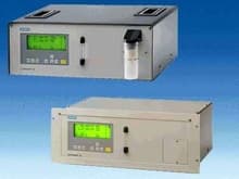
 TheULTRAMAT 23 gas analyzer can measure up to 4 gas components at once: A maximum of three infrared sensitive gases such as CO, CO2, NO, SO2, CH4 and in addition O2 with an electrochemical oxygen measuring cell.
ULTRAMAT 23 basic versions for:
- 1 infrared gas component with/without oxygen measurement
- 2 infrared gas components with/without oxygen measurement
- 3 infrared gas components with/without oxygen measurement.
ULTRAMAT 23
Особенности
- AUTOCAL with ambient air (depends on measured component) High efficiency so no calibration gas and accessories required
- High selectivity by multiple layer detectors, e.g. small cross sensitivity to water vapor
- Cleanable sample cells, cost saving in further use in case of pollution
- Menu-assisted operation in plain text, operation control without manual, high operator safety
- Service information and log book, preventive maintenance; help for service and maintenance personnel, cost reduction
- Coded operator level against unauthorized access, increased safety
- Open interface architecture (RS 485, RS 232; PROFIBUS, SIPROM GA) simplified process integration, remote control.
Область применения
Application areas
- Optimization of small firing systems
- Monitoring of exhaust gas concentration from firing systems with all types of fuel (oil, gas and coal) as well as operational measurements with thermal incineration plants
- Room air monitoring
- Monitoring of air in fruit stores, greenhouses, fermenting cellars and warehouses
- Monitoring of process control functions
- Atmosphere monitoring during heat treatment of steel
- For use in non-potentially explosive atmospheres.
Further applications
- Environmental protection
- Chemical plants
- Cement industry.
Special applications
- Separate gas paths The ULTRAMAT 23 with 2 IR components without pump is also available with two separate gas paths. This allows the measurement of two measuring points as used e.g. for the NOx measurement before and after the NOx converter. The ULTRAMAT 23 gas analyzer can be used in emission measuring systems and for process and safety monitoring.
- TÜV version TÜV-approved versions of the ULTRAMAT 23 are available for measurement of CO, NO, SO2 and O2 according to 13. BImSchV and TA Luft. Smallest TÜV-approved and permitted measuring ranges:
- 1- and 2-component analyzer CO: 0 to 150 mg/m3 NO: 0 to 100 mg/m3 SO2: 0 to 400 mgm3
- 3-component analyzer CO: 0 to 250 mg/m3 NO: 0 to 400 mg/m3 SO2: 0 to 400 mg/m3
All larger measuring ranges are also approved.
Furthermore, the TÜV-approved versions of the ULTRAMAT 23 comply with the requirements of EN 14956 and of QAL 1 according to EN 14181. Conformity of the analyzers with both standards is TÜV-certified.
Determination of the analyzer drift according to EN 14181 (QAL 3) can be carried out manually or also with a PC using the SIPROM GA maintenance and servicing software. In addition, selected manufacturers of emission evaluation computers offer the possibility for downloading the drift data via the analyzer’s serial interface and to automatically record and process them in the evaluation computer.
- Version with reduced response time The connection between both condensation traps is equipped with a stopper to lead the complete flow through the measuring cell (otherwise only 1/3 of the flow), i.e. the response time is 2/3 faster. The functions of all other components are unchanged.
- Chopper compartment flushing: consumption100 ml/min.
Дизайн
- 19“ unit with 4 HU for installation
- in swing frame
- in cabinets, with or without slide rails
- Flowmeter for sample gas on front panel; Option: integrated sample gas pump (standard for bench-top version).
- Gas connections for sample gas input and output as well as zero gas; pipe diameter 6 mm or ¼“
- Gas and electrical connections at the rear (portable version: sample gas inlet at front).
Display and control panel
- Operation according to NAMUR recommendation
- Simple, fast programming and commissioning of analyzer
- Large, backlit LCD for measured values
- Menu-based inputs for parametrization, test functions and calibration
- Washable membrane keypad
- User help in plain text
- Operation software in 6 languages.
Inputs and outputs
- Three binary inputs for sample gas pump On/Off, triggering of AUTOCAL and synchronization of several devices
- Eight relay outputs can be freely configured for fault, maintenance request, maintenance switch, limits, range identification and external solenoid valves
- Eight additional binary inputs and relay outputs as an option
- Electrically isolated analog outputs.
Communication
- RS 485 present in basic unit (connection from the rear).
Options
- RS 485/RS 232 converter
- RS 485/Ethernet converter
- Incorporation in networks via PROFIBUS DP/PA interface
- SIPROM GA software as service and maintenance tool.
ULTRAMAT 23, membrane keypad and graphic display
Executions of the wetted parts
| Gas path | 19“ unit | Desktop unit | |
|---|---|---|---|
| With hoses | Condensation trap/gas inlet | - | PA (polyamide) |
| Condensation trap | - | PE (polyethylene) | |
| Gas nipples 6 mm | PA (polyamide) | PA (polyamide) | |
| Gas nipples ¼“ | SS, type No. 1.4571 | SS, type No. 1.4571 | |
| Hose | FPM (Viton) | FPM (Viton) | |
| Pressure switch | FPM (Viton) + PA6-3-T (Trogamide) | FPM (Viton) + PA6-3-T (Trogamide) | |
| Flowmeter | PDM/Duran glass/X10CrNiTi1810 | PDM/Duran glass/X10CrNiTi1810 | |
| Elbows/T-pieces | PA6 | PA6 | |
| Internal pump | PVDF/PTFE/EPDM/FPM/Trolene/ SS, type No. 1.4571 | PVDF/PTFE/EPDM/FPM/Trolene/ SS, type No. 1.4571 | |
| Solenoid valve | FPM70/Ultramide/1.4310/1.4305 | FPM70/Ultramide/1.4310/1.4305 | |
| Safety reservoir | PA66/NBR/PA6 | PA66/NBR/PA6 | |
| Sample cell | |||
| - Body | Aluminium | Aluminium | |
| - Cell lining | Aluminium | Aluminium | |
| - Stub | SS, type No. 1.4571 | SS, type No. 1.4571 | |
| - Window | CaF2 | CaF2 | |
| - Adhesive | E353 | E353 | |
| - O-ring | FPM (Viton) | FPM (Viton) | |
| With pipes | Gas nipples (6 mm / ¼“) | SS, type No. 1.4571 | |
| Pipes | SS, type No. 1.4571 | ||
| Sample cell | |||
| - Body | Aluminium | ||
| - Cell lining | Aluminium | ||
| - Stub | SS, type No. 1.4571 | ||
| - Window | CaF2 | ||
| - Adhesive | E353 | ||
| - O-ring | FPM (Viton) |
ULTRAMAT 23, design
Gas path
| Key to gas path figures | |||
|---|---|---|---|
| 1 | Inlet fo sample gas/ calibration gas | 9 | Safety fine filter |
| 2 | Gas outlet | 10 | Solenoid valve |
| 3 | Inlet for AUTOCAL/zero gas or Inlet for sample gas/ adjusting gas (channel 2) | 11 12 | Sample gas pump Pressure switch |
| 4 | Gas outlet (channel 2) | 13 | Flowmeter |
| 5 | Enclosure flushing | 14 | Analyzer section |
| 6 | Inlet atmospheric pressure sensor | 15 | Safety condensate trap |
| 7 | Inlet housing/chopper compartment flushing | 16 | Oxygen measuring cell |
| 8 | Condensation trap with filter | 17 | Atmospheric pressure sensor |
ULTRAMAT 23, portable, in sheet-steel housing with internal sample gas pump, condensation trap with safety filter on front panel, optional oxygen measurement
ULTRAMAT 23, 19“ unit with internal sample gas pump, optional oxygen measurement
ULTRAMAT 23, 19“ unit without internal sample gas pump, optional oxygen measurement
ULTRAMAT 23, 19“ unit without internal sample gas pump, with separate gas path for the second component or for the 2nd and 3rd components, optional oxygen measurement
ULTRAMAT 23, 19“ unit, sample gas path version in pipes, optional separate gas path, always without sample gas pump, without safety filter and without safety trap
Функции
Two independent, selective measuring principles are used in the ULTRAMAT 23.
Infrared measurement
An IR source (7) at 600 °C emits an infrared radiation which is modulated with 8 1/3 Hz by a chopper (5). After passing the sample cell (4), the intensity of the radiation is measured by the detector (11, 12).
The represented detector is composed of layers filled with the component to be analyzed. The energy of the middles of the IR bands of the measured gases is mainly absorbed in the first layer. The second layer absorbs the edge energy which is tuned on high selectivity in the third layer via an aperture.
When passing through the layers the radiation absorption results in different pressure increases and so to a flow via the capillary hole. The microflow sensor there generates a signal which is nearly independent of interferences from components at the band edges.
Note
The sample gases have to enter the analyzer dustfree. Avoid condensate in the sample cells. Therefore an appropriated gas preparation is required depending of the applications.
The ambient air of the analyzer should be, in a large extent, free of high concentrations of the component to be measured.
ULTRAMAT 23, mode of operation of infrared channel (example with three-layer detector)
Automatic calibration with air
The ULTRAMAT 23 can be calibrated e.g. with ambient air. During this AUTOCAL (adjustable between 0 and 24 hours), the chamber is purged with air. The detector then generates the largest signal U0 (no pre-absorption in the sample chamber). This signal is used as the reference for the zero calibration and serves simultaneously as the initial value for calculation of the full-scale value in the manner described below.
The absorption in the sample chamber increases along with the concentration of the measured component. As a result of this pre-absorption, the radiation energy measured in the detector decreases, and thus also the signal voltage. The mathematical relationship between the concentration of the measured component and the signal voltage corresponds to a good approximation in the single-beam procedure of the ULTRAMAT 23 to an exponential function of form:
U = U 0 · e -kc
c Concentration
k Device-specific constant
U0 Basic signal with zero gas (sample gas without measured component)
U Detector signal
Changes in the radiated power, contamination of the sample chamber, or ageing of detector components have the same effect on both U0 and U, and result in:
U**’ = U’**0 · e-kc
Apart from being dependent on the concentration c, the measured voltage therefore changes continuously with increased ageing of the radiator or with persistent contamination.
The mentioned influences of contamination and ageing will have a negligible effect on the measurement as long as U’ remains within a certain tolerance range which is monitored by the analyzer.
The analyzers carry out automatic calibration of the zero point with ambient air every 1, 2, 3 ... 24 hours as desired. Calibration with a calibration gas is unnecessary since the calibration curve is calculated with the new U’0 value.
ULTRAMAT 23, mode of operation of oxygen measuring cell
Oxygen measurement
The oxygen sensor operates according to the principle of a fuel cell. The oxygen is converted at the boundary layer between cathode and electrolyte; the resulting current is proportional to the concentration of oxygen.
This sensor version with an acid based electrolyte is less sensitive to cross interferences, especially CO2, CO, CH4 and H2 than other sensor types.
Essential characteristics
- Practically maintenance-free as a result of AUTOCAL with ambient air (or with N2, only with units without oxygen sensor); both the zero and the span are calibrated in the process
- Calibration with calibration gas is only necessary every 12 months, depending on application
- Two measuring ranges can be set per component within defined limits; all measuring ranges linearized; autoranging with range identification
- Automatic correction of variations in atmospheric pressure
- Gas flow monitoring; Low-flow alarm at 1 l/min (with viton sample gas path only)
- Maintenance request alert
- Two limits can be freely configured for each component, for upward or downward violation.