
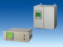
 The OXYMAT 6 gas analyzers are based on the paramagnetic alternating pressure method and are used to measure oxygen in gases.
19” unit and field unit
Особенности
- Paramagnetic alternating pressure principle
- Small measuring ranges (0-0.5% or 99.5-100% O2)
- Absolute linearity
- Detector element has no contact with the samples gas
- Can be used to measure corrosive gases
- Long lifetime
- Physically suppressed zero through suitable selection of reference gas (air or O2), e.g. 98-100% O2 for purity monitoring / air separation
- Open interface architecture (RS 485, RS 232, PROFIBUS)
- SIPROM GA network for maintenance and servicing information (option)
- Electronics and physics: gas-tight isolation, purging is possible, IP65, high service life even in harsh environments
- Heated versions (option), use also in presence of gases condensing at low temperature (field unit only)
- EEx(p) for zones 1 and 2 according to ATEX 2G and ATEX 3G (field unit only).
Область применения
- For boiler control in firing systems
- In safety-relevant areas
- As a reference variable for emission measurements according to TA-Luft, 13. and 17. BImSchV
- In the automotive industry (engine test systems)
- Warning equipment
- In chemical plants
- In ultra-pure gases for quality monitoring
- Environmental protection
- Quality monitoring
- Inert gas monitoring as certified gas warning equipment (DMT)
- Version to analyze flammable and non-flammable gases or vapors for use in hazardous areas.
Special applications
Besides the standard combinations special applications concerning material in the gas path and material of the sample cells are available on request.
Дизайн
19“ unit
- With 4HU for installation
- in swing frame
- in cabinets, with or without slide rails
- Front panel for service can be hinged down (laptop connection)
- Internal gas paths: flexible tube made of FKM (Viton) or pipe made of titanium or stainless steel (SS, type No. 1.4571)
- Gas connections for sample gas input and output and for reference gas: stubs, pipe diameter 6 mm or 1/4"
- Flowmeter for sample gas on the front panel (option).
Field unit
- Two-door housing with gas-tight separation of analyzer and electronics sections
- Each half of the enclosure can be purged separately
- Analyzer section and piping can be heated up to 130 °C (option)
- Gas path and stubs made of stainless steel (type No. 1.4571) or titanium, Hastelloy C22
- Purging gas connections: pipe diameter 10 mm or 3/8"
- Gas connections for sample gas input and output and for reference gas: clamping ring connection for pipe diameter 6 mm or 1/4".
Display and control panel
- Large LCD panel for simultaneous display of:
- Measured value (digital and analog displays)
- Status line
- Measuring ranges
- Contrast of LCD panel adjustable using menu
- Permanent LED backlighting
- Washable membrane keyboard with five softkeys
- Menu-based operation for configuration, test functions, calibration
- User help in plain text
- Graphic display of concentration trend; programmable time intervals
- Operation software in two languages: German/English, English/French, French/English, Spanish/English, Italian/English.
Inputs and outputs
- One analog output
- Two analog inputs programmable (e.g. correction of cross interferences or external pressure sensor)
- Six binary inputs freely configurable (e.g. for range switching, processing external signals from sample conditioning)
- Six relay outputs freely configurable (e.g. failure, maintenance request, maintenance switch, limit alarm, external solenoid valves)
- Extension with eight additional binary inputs and eight additional relay outputs, e.g. for automatic calibration with up to four calibration gases.
Communication
- RS 485 present in basic unit (connection at the rear; with 19“ unit also possibility of connection behind the front plate).
Options
- AK interface for the automotive industry with extended functions
- RS 485/RS 232 converter
- RS 485/Ethernet converter
- Linking to networks via PROFIBUS DP/PA interface
- SIPROM GA software as service and maintenance tool.
OXYMAT 6, membrane keyboard and graphic display
Versions– Wetted parts
Standard
| Gas path | 19“ unit | Field unit | Field unit Ex | |
|---|---|---|---|---|
| With hoses | Nipple Hose Sample cell Stubs sample cell Restrictor O-rings | SS, type No. 1.4571 FKM (e.g. Viton) SS, type No. 1.4571 or Ta SS, type No. 1.4571 PTFE (e.g. Teflon) FKM (e.g. Viton) | - | - |
| With pipes | Nipple Pipe Sample cell Restrictor O-rings | Titanium Titanium SS, type No. 1.4571 or tantalum Titanium FKM (Viton) or FFKM (e.g. Kalrez) | ||
| With pipes | Nipple Pipe Sample cell Restrictor O-rings | SS, type No. 1.4571 SS, type No. 1.4571 SS, type No. 1.4571 or tantalium SS, type No. 1.4571 FKM (Viton) or FFKM (Kalrez) | ||
| With pipes | Nipple Pipe Sample cell Restrictor O-rings | Hastelloy C 22 Hastelloy C 22 SS, type No. 1.4571 or tantalum Hastelloy C 22 FKM (e.g.Viton) or FFKM (e.g. Kalrez) |
Options
| Options | ||||
|---|---|---|---|---|
| Flowmeter | Metering pipe Float Float limit Elbows | Duran glass Duran glass, black PTFE (Teflon) FKM (Viton) | - | - |
| Pressure switch | Membrane Enclosure | FKM (Viton) PA 6.3 T | - | - |
Gas path (19“ unit)
| Key to gas path figures | |||
|---|---|---|---|
| 1 | Sample gas inlet | 8 | Pressure switch in sample gas path (option) |
| 2 | Sample gas outlet | 9 | Purging gas |
| 3 | Not used | 10 | Pressure switch in reference gas path (option) |
| 4 | Reference gas inlet with outlet restrictor | 11 | Pressure sensor |
| 5 | Restrictor in reference gas inlet | 12 | Filter |
| 6 | O2 bench | 13 | Flowmeter in sample gas path (option) |
| 7 | Restrictor in sample gas path |
Gas path, reference gas connection 2000 to 4000 hPa
Gas path, reference gas connection100 hPa
Gas path (field unit)
| Key to gas path figures | |||
|---|---|---|---|
| 1 | Not used | 7 | Purging gas outlet (analyzing side) |
| 2 | Sample gas inlet | 8 | Purging gas inlet (analyzing side) |
| 3 | Reference gas inlet | 9 | Pressure sensor |
| 4 | Sample gas outlet | 10 | O2 bench |
| 5 | Purging gas inlet (electronic side) | 11 | Restrictor in sample gas path |
| 6 | Purging gas outlet (electronic side) | 12 | Flowmeter in reference gas path |
Gas path, reference gas connection 100 hPa
Gas path, reference gas connection 2000 to 4000 hPa
Функции
Mode of operation
In contrast to almost all other gases, oxygen is paramagnetic. This property is utilized as the measuring principle by the OXYMAT 6 gas analyzers.
Oxygen molecules in an inhomogeneous magnetic field are drawn in the direction of increased field strength due to their paramagnetism. When two gases with different oxygen concentrations meet in a magnetic field, a pressure difference is produced between them.
In the case of OXYMAT 6, one gas (1) is a reference gas (N2, O2 or air), the other is the sample gas (5). The reference gas is introduced into the sample cell (6) through two channels (3). One of these reference gas streams meets the sample gas within the area of a magnetic field (7). Because the two channels are connected, the pressure, which is proportional to the oxygen concentration, causes a cross flow. This flow is converted into an electric signal by a microflow sensor (4).
The microflow sensor consists of two nickel grids heated to approx. 120 ºC which form a Wheatstone bridge together with two supplementary resistors. The pulsating flow results in a change in the resistance of the Ni grids. This results in a bridge offset which depends on the oxygen concentration in the sample gas.
Because the microflow sensor is located in the reference gas stream, the measurement is not influenced by the thermal conductivity, the specific heat or the internal friction of the sample gas. This also provides a high degree of corrosion resistance because the flow sensor is not exposed to the direct influence of the sample gas.
By using a magnetic field with alternating strength (8), the effect of the background flow in the microflow sensor is not detected, and the measurement is thus independent of the instrument orientation.
The sample cell is directly in the sample path and has a small volume. The microflow sensor thus responds quickly, resulting in a very short response time for the OXYMAT 6.
Vibrations frequently occur at the place of measurement and may falsify the measured signal (noise). A further microflow sensor (10) through which no gas passes acts as a vibration sensor. Its signal is applied to the measured signal as compensation.
If the density of the sample gas deviates by more than 50% from that of the reference gas, the compensation microflow sensor (10) is flushed with reference gas just like the measuring sensor (4).
Note
The sample gas needs to be free of dust. Condensate in the cells must be avoided. That is why the most measuring tasks require an appropriate gas preparation.
OXYMAT 6, mode of operation
Essential characteristics
- Four freely parameterizable measuring ranges, also with zero offset, all measuring ranges linear
- Measuring ranges with physical zero offset possible
- Measuring range identification
- Electrically isolated signal output selectable as 0/2/4 to 20 mA (also inverted)
- Autoranging or manual range switching possible; remote switching is also possible
- Storage of measured values possible during adjustments
- Time constants selectable within wide limits (static/dynamic noise suppression); i.e. the response time of the analyzer can be matched to the respective application
- Short response time
- Low long-term drift
- Measuring-point selection for up to 6 measuring points (programmable)
- Measuring point identification
- Internal pressure sensor for correction of pressure variations in sample gas (range 500 to 2000 hPa absolute)
- External pressure sensor can be connected for correction of variations in sample gas pressure up to 3000 hPa absolute (option)
- Monitoring of sample gas flow (option for viton tubed version)
- Monitoring of sample gas and/or reference gas (option)
- Monitoring of reference gas with reference gas connection 2000 to 4000 hPa (option)
- Automatic range calibration can be parameterized
- Operation based on NAMUR Recommendation
- Two-stage access code to prevent unintentional and unauthorized inputs
- Simple handling using a numerical membrane keypad including operator prompting
- Customer-specific analyzer options such as e.g.:
- Customer acceptance
- Tag labels
- Drift recording
- Clean for O2-Service
- Kalrez gaskets
- Analyzer section with flow-type compensation circuit: a flow is passed through the compensation branch (option) to reduce the vibration dependency in the case of highly different densities of the sample and reference gases
- Sample cell for use in presence of highly corrosive sample gases.
Reference gases
| Measuring range | Recommended reference gas | Reference gas connection pressure | Remarks |
|---|---|---|---|
| 0 to . . . % v/v O2 | N2 | 2000 to 4000 hPa above sample gas pressure (max. 5000 hPa absolute) | The reference gas flow is set automatically to 5 to 10 ml/min (up to 20 ml/min when also flowing through compensation branch) |
| O2 | |||
| . . . to 100% v/v O2 (suppressed zero with full-scale value 100% v/v O2) | Air | 100 hPa with respect to sample gas pressure which may vary by max. 50 hPa around the atmospheric pressure | |
| Around 21% v/v O2 (suppressed zero with 21% v/v O2 within the span) |
Table 1 Reference gases for OXYMAT 6
Correction of zero error / Cross interferences
| Residual gas (concentration 100% v/v) | Zero deviation in % v/v O2 absolute | Residual gas (concentration 100% v/v) | Zero deviation in % v/v O2 absolute |
|---|---|---|---|
| Organic gases | Inert gases | ||
| Acetic acid CH3COOH | -0.64 | Argon | -0.25 |
| Acetylene C2H2 | -0.29 | Helium | +0.33 |
| 1,2 butadiene C4H6 | -0.65 | Krypton | -0.55 |
| 1,3 butadiene C4H6 | -0.49 | Neon | +0.17 |
| iso-butane C4H10 | -1.30 | Xenon | -1.05 |
| n-butane C4H10 | -1.26 | ||
| 1-butene C4H6 | -0.96 | Anorganic gases | |
| iso-butene C4H8 | -1.06 | Ammonia | -0.20 |
| Cyclo-hexane C6H12 | -1.84 | Carbon dioxide | -0.30 |
| Dichlorodifluoromethane (R12) CCl2F2 | -1.32 | Carbon monoxide | +0.07 |
| Ethane C2H6 | -0.49 | Chlorine | -0.94 |
| Ethylene C2H4 | -0.22 | Dinitrogen monoxide | -0.23 |
| n-heptane C7H16 | -2.4 | Hydrogen | +0.26 |
| n-hexane C6H14 | -2.02 | Hydrogen bromide | -0.76 |
| Methane CH4 | -0.18 | Hydrogen chloride | -0.35 |
| Methanol CH3OH | -0.31 | Hydrogen fluoride | -0.10 |
| n-octane C8H18 | -2.78 | Hydrogen iodide | -1.19 |
| n-pentane C5H12 | -1.68 | Hydrogen sulphide | -0.44 |
| iso-pentane C5H12 | -1.49 | Oxygen | +100 |
| Propane C3H8 | -0.87 | Nitrogen | 0.00 |
| Propylene C3H6 | -0.64 | Nitrogen dioxide | +20.00 |
| Trichlorofluoromethane (R11) CCl3F | -1.63 | Nitrogen oxide | +42.94 |
| Vinyl chloride C2H3Cl | -0.77 | Sulphur dioxide | -0.20 |
| Vinyl fluoride C2H3F | -0.55 | Sulphur hexafluoride | -1.05 |
| 1,1 vinylidene chloride C2H2Cl2 | -1.22 | Water | -0.03 |
Table 2 Zero error due to diamagnetism or paramagnetism of residual gases with nitrogen as the reference gas at 60 °C and 1000 hPa absolute (according to IEC 1207/3)
Conversion to other temperatures:
The zero errors mentionned in Table 2 must be multiplied with a correction factor (k):
- with diamagnetic gases: k = 333 K / (ϑ [°C] + 273 K)
- with paramagnetic gases: k = [333 K / (ϑ [°C] + 273 K)]2
(all diamagnetic gases have a negative zero error).