
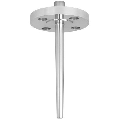
Термокарман із фланцем
Опис
Кожна термогільза/захисна трубка є важливим компонентом будь-якого пункту вимірювання температури. Вона використовується для відокремлення технологічного процесу від навколишнього середовища, тим самим захищаючи довкілля та обслуговуючий персонал, а також запобігає впливу агресивних середовищ, високих тисків і витрат потоку безпосередньо на температурний датчик. Це, у свою чергу, дає змогу виконувати заміну термометра під час роботи.
З огляду на майже необмежені можливості застосування існує велика кількість варіантів, зокрема конструкцій термогільз/захисних трубок або матеріалів. Тип технологічного приєднання та базовий метод виготовлення є важливими критеріями розрізнення конструкцій. Базове розрізнення можна виконати між термогільзами/захисними трубками з різьбовим приєднанням і такими, що приварюються, а також тими, що мають фланцеві приєднання.
Особливості
- Виконання для важких умов експлуатації
- Покриття для корозійних або абразивних робочих середовищ
- Можливі форми захисних гільз: конічна, пряма, ступінчаста
Питання та відповіді
Для яких галузей підходить термокарман TW10?
Він призначений для нафтохімічної промисловості, on-/offshore застосувань і будівництва промислових установок, зокрема для точок з високими навантаженнями у процесі.
Чим TW10 відрізняється від звичайних термокарманив?
Це важконавантажена (heavy-duty) суцільнооброблена конструкція з фланцевим приєднанням, розрахована на високі процесні та хімічні навантаження.
Які матеріали доступні для термогільзи?
Нержавіючі сталі 304/304L, 316/316L, 1.4571, 1.4404, вуглецева сталь A105, сплави C4, C276 і 400, титан grade 2 та танталовий лист.
Які варіанти приєднання до процесу передбачені?
Фланці за стандартами ASME B16.5, EN 1092-1 та DIN 2527, а також різьбові варіанти M20 x 1.5, ½ NPT внутрішнє різьблення та G ½ внутрішнє різьблення.
Які форми термогільзи можна обрати?
Конічну, пряму, ступеневу, а також форму ScrutonWell.
Як захистити гільзу від корозії чи абразивного зносу?
Передбачене покриття термогільзи для корозійних або абразивних навантажень у процесі.
Чи можна замінити термометр без зупинки процесу?
Так: термокарман відокремлює температурний датчик від середовища, що дає змогу виконувати заміну термометра під час роботи установки.
Зберіть TW10 під свою задачу
Артикул збирається автоматично. Якщо сумніваєтесь — напишіть інженеру; підкажемо за параметрами лінії.
- Welding optionsЗварювання з повним проваром
- Thermowell styleКонічний
- Unit of measureМетричний (мм)
- Flange sizeASME 1 дюйм
- Pressure ratingКлас 150
- Flange faceRF (Raised face)
- Connection to thermometer [N]1/2 NPT female
- Pipe sched. /Intern. nozzle dia.WIKA (Стандарт Німеччини)
- Insertion length [U]150
- Head length [H]57
- Flange materialНержавіюча сталь 316/316L
- MaterialНержавіюча сталь 316/316L
- Bar diameter [Bd or F2]30 mm
- Bore size [B or d1]—
- Root diameter [Q]22,0
- Tip diameter [V or F3]—
- Certificates—
Завершіть конфігурацію
Оберіть всі параметри, щоб надіслати запит.
| Модель | TW10 |
| Сімейство | TW |
| Підтип | Flanged thermowell |
| Технологічне приєднання | ASME B16.5EN 1092-1DIN 2527M20 x 1.5½ NPT female threadG ½ female thread |
| Матеріал захисної гільзи | Stainless steel 304/304L, Stainless steel 316/316L, Stainless steel 1.4571, Stainless steel 1.4404, A105, Alloy C4, Alloy C276, Alloy 400, Titanium grade 2, Tantalum sheet |
| Захисна гільза | Так |
| Форма захисної гільзи | tapered, straight, stepped, ScrutonWell |
| Мови datasheet | EN |
| Basic information | |
|---|---|
| Thermowell form | ■ Tapered ■ Straight ■ Stepped ■ ScrutonWell design per SP 05.16 (selectable) |
| Versions | |
| DesignTW10-F | Full penetration weld version |
| DesignTW10-P | With double weld seam (weld seam strength 3 mm) |
| DesignTW10-R | With double weld seam (weld seam strength 6 mm) |
| DesignTW10-S | Screw-welded design, weld seam does not come into direct contact with the medium |
| DesignTW10-B | Screw-welded design, additional weld seam on the process side (sealing joint) |
| DesignTW10-W | Forged version without welded joint |
| Material (wetted) | ■ Stainless steel 304/304L ■ Stainless steel 316/316L ■ Stainless steel 1.4571 ■ Stainless steel 1.4404 ■ A105 ■ Alloy C4 ■ Alloy C276 ■ Alloy 400 ■ Titanium grade 2 1) ■ Tantalum sheet for wetted parts ■ Restricted choice of materials withTW10-W |
| Coating | |
| Hardfacing for abrasive process loads with Stellite ® 6 | ■ Laser cladding Layer thickness 1.6 mm[0.062 in] (standard) Higher layer thickness on request ■ Plasma Transfer Arc (PTA) Layer thickness 1.6 mm[0.062 in] (standard) up to 3.2 mm[0.125 in] ■ Air Plasma Spraying (APS) Layer thickness max. 1.6 mm[0.062 in] ■ High Velocity Oxide Fuel (HVOF) Layer thickness 0.5 mm[0.02 in] |
| Corrosion protection for high chemical loads | ■ PFA Layer thickness min. 0.4 mm[0.015 in] (standard) or min. 0.6 mm[0.024 in] (special design) ■ ECTFE (Halar ® ) Layer thickness min. 0.6 mm[0.024 in] → Other resistant coatings on request |
| Process connection | |
|---|---|
| Type of process connection | |
| Flange | ■ Per ASME B16.5 ■ Per EN 1092-1 ■ Per DIN 2527 → Other flanges on request |
| TW10-W | ■ Dimensions in accordance with ASME B16.5 ■ Dimensions in accordance with EN 1092-1 ■ Dimensions in accordance with DIN 2527 |
| Connection to thermometer N | ■ ½NPTfemale thread ■ G½female thread ■ M20 x 1.5 |
| Bore size B | ■ 6.2 mm[0.244 in] ■ 6.6 mm[0.260 in] ■ 7.0 mm[0.276 in] ■ 8.2 mm[0.323 in] ■ 8.5 mm[0.355 in] ■ 9.0 mm[0.354 in] ■ 9.8 mm[0.385 in] ■ 10.2 mm[0.402 in] ■ 12.2 mm[0.480 in] |
| Insertion length U | ■ 150 mm[5.9 in] ■ 200 mm[7.87 in] ■ 250 mm[9.84 in] ■ 300 mm[11.81 in] ■ 350 mm[13.78 in] ■ 400 mm[15.75 in] ■ 6 in [152 mm] ■ 7 in [178 mm] ■ 10 in [254 mm] ■ 13 in [330 mm] ■ 16 in [406 mm] |
| → Other insertion lengths on request | |
| Min. insertion length | Depending on the selected version |
| Max. insertion length 1) | 800 mm[31.5 in] |
| Connection length H | ■ 45 mm[1.77 in] ■ 57 mm[2.25 in] ■ 60 mm[2.36 in] ■ 83 mm[3.25 in] ■ 108 mm[4.25 in] ■ 133 mm[5.25 in] → Other connection lengths on request |
| Min. Connection length Max. Connection length | Depending on the selected version 250 mm[10 in] |
| Version | AARH in µinch | Ra in µm | Rz in µm | |
|---|---|---|---|---|
| Sealing face roughness | ||||
| ASME B16.5 | Stock finish | 125 ... 250 | 3.2 ... 6.3 | - |
| Smooth finish | < 125 | < 3.2 | - | |
| RTJ | < 63 | < 1.6 | - | |
| Tongue/groove | < 125 | < 3.2 | - | |
| EN 1092-1 | Form B1 | - | 3.2 ... 12.5 | 12.5 ... 50 |
| Form B2 | - | 0.8 ... 3.2 | 3.2 ... 12.5 | |
| DIN 2527 | Form C | - | - | 40 ... 160 |
| Form E | - | - | < 16 |
| Max. process temperature, process pressure | Depending on: ■ Thermowell design - Dimensions - Material - Coating - Flange pressure rating ■ Process conditions - Flow rate - Density of medium |
|---|---|
| Wake frequency calculation (option) | The calculation in accordance with ASME PTC 19.3 TW-2016 of individual thermowells minimises the risk of dynamic damage that can be caused by the vortex shedding of a Kármán vortex street (Vortex Induced Vibration; VIV). In addition, the static loads due to lateral flow and the process pressure are calculated depending on the temperature. The calculation can be carried out independently using an online tool or as aWIKA engineered service (subject to charges). → |
| For further information see Technical information IN 00.15 'Wake frequency calculation'. |
Переглянути всі (8)
| DN | PN in lbs | Dimensions in mm[in] | Weight in kg [lbs] (approx.) | ||||
|---|---|---|---|---|---|---|---|
| H | Ø Q | ØV | U = 4" | U = 13" | U = 22" | ||
| 1" | 150 | approx. 57 [2 ¼] | 22 [0.875] | 16 [0.625] | 1.4 [3.086] | 1.9 [4.188] | 2.3 [5.070] |
| 300 | approx. 57 [2 ¼] | 22 [0.875] | 16 [0.625] | 2.1 [4.629] | 2.6 [5.732] | 3.0 [6.613] | |
| 600 | approx. 57 [2 ¼] | 22 [0.875] | 16 [0.625] | 2.3 [5.070] | 2.8 [6.172] | 3.2 [7.054] | |
| 1,500 | approx. 83 [3 ¼] | 22 [0.875] | 16 [0.625] | 4.3 [9.479] | 4.8 [10.582] | 5.2 [11.464] | |
| 2,500 | approx. 83 [3 ¼] | 22 [0.875] | 16 [0.625] | 5.6 [12.345] | 6.1 [13.448] | 6.5 [14.330] | |
| 1 ½" | 150 | approx. 57 [2 ¼] | 25 [1.000] | 19 [0.750] | 1.8 [3.968] | 2.4 [5.291] | 3.0 [6.613] |
| 300 | approx. 57 [2 ¼] | 25 [1.000] | 19 [0.750] | 3.3 [7.275] | 3.9 [8.598] | 4.5 [9.920] | |
| 600 | approx. 57 [2 ¼] | 25 [1.000] | 19 [0.750] | 4.0 [8.818] | 4.7 [10.361] | 5.3 [11.684] | |
| 1,500 | approx. 83 [3 ¼] | 25 [1.000] | 19 [0.750] | 6.4 [14.109] | 7.1 [15.652] | 7.7 [16.975] | |
| 2,500 | approx. 83 [3 ¼] | 25 [1.000] | 19 [0.750] | 12.0 [26.455] | 12.6 [27.778] | 13.3 [29.321] | |
| 2" | 150 | approx. 57 [2 ¼] | 25 [1.000] | 19 [0.750] | 2.5 [5.511] | 3.1 [6.834] | 3.7 [8.157] |
| 300 | approx. 57 [2 ¼] | 25 [1.000] | 19 [0.750] | 3.7 [8.157] | 4.3 [9.479] | 4.9 [10.802] | |
| 600 | approx. 57 [2 ¼] | 25 [1.000] | 19 [0.750] | 4.2 [9.259] | 4.9 [10.802] | 5.5 [12.125] | |
| 1,500 | approx. 83 [3 ¼] | 25 [1.000] | 19 [0.750] | 11.0 [24.250] | 11.6 [25.573] | 12.3 [27.116] | |
| 2,500 | approx. 108 [4 ¼] | 25 [1.000] | 19 [0.750] | 17.0 [37.478] | 17.6 [38.801] | 18.3 [40.344] |
| DN | PN in bar | Dimensions in mm[in] | Weight in kg [lbs] (approx.) | |||
|---|---|---|---|---|---|---|
| H | Ø Q | ØV | U = 160mm | U = 500mm | ||
| 25 | 40 | 45 [1.771] | 22 [0.875] | 16 [0.625] | 1.9 [4.188] | 2.6 [5.732] |
| 63/64 | 45 [1.771] | 22 [0.875] | 16 [0.625] | 3.2 [7.054] | 3.9 [8.598] | |
| 100 | 45 [1.771] | 22 [0.875] | 16 [0.625] | 3.2 [7.054] | 3.9 [8.598] | |
| 40 | 40 | 45 [1.771] | 25 [1.000] | 19 [0.750] | 3.1 [6.834] | 4.0 [8.818] |
| 63/64 | 45 [1.771] | 25 [1.000] | 19 [0.750] | 4.8 [10.582] | 5.7 [12.566] | |
| 100 | 45 [1.771] | 25 [1.000] | 19 [0.750] | 4.8 [10.582] | 5.7 [12.566] | |
| 50 | 40 | 45 [1.771] | 25 [1.000] | 19 [0.750] | 3.9 [8.598] | 4.8 [10.582] |
| 63/64 | 45 [1.771] | 25 [1.000] | 19 [0.750] | 5.2 [11.464] | 6.1 [13.448] | |
| 100 | 45 [1.771] | 25 [1.000] | 19 [0.750] | 6.6 [14.550] | 7.5 [16.534] | |
| 80 | 40 | 60 [2.362] | 25 [1.000] | 19 [0.750] | 6.6 [14.550] | 7.5 [16.534] |
| 63/64 | 60 [2.362] | 25 [1.000] | 19 [0.750] | 7.6 [16.755] | 8.5 [18.739] | |
| 100 | 60 [2.362] | 25 [1.000] | 19 [0.750] | 10.2 [22.487] | 11.1 [24.471] | |
| 100 | 40 | 60 [2.362] | 25 [1.000] | 19 [0.750] | 8.3 [18.298] | 9.2 [20.282] |
| 63/64 | 60 [2.362] | 25 [1.000] | 19 [0.750] | 10.9 [24.030] | 11.8 [26.014] | |
| 100 | 60 [2.362] | 25 [1.000] | 19 [0.750] | 15.0 [33.069] | 15.9 [35.053] |
| TW10 | Thermowell with flange |
|---|---|
| TW15/TW50 | Threaded thermowell |
| TW20 | Weld-in thermowell (for welding socket) |
| TW25 | Weld-in thermowell (variable welding diameter) |
| TW30 | Thermowell in Vanstone design for lap flanges |
| Dimensions in mm[in] Surface texture z y x Tol. ISO 2768 - mK 0,5 ...6 >6 >30 >120 ...30 ...120 ...400 Check indicator language nominal size | Root diam- eter mm [inch] units SIZE ISO 14405 8015 Nur zur DR comments | Tip diam- eter www.wika.com D-63911 Klingenberg ALEXANDER WIEGAND SE & Co. KG Information sheets 1 / 1 | Strake height | Strake depth | Scruton length 1) | Insertion length 1) |
|---|---|---|---|---|---|---|
| - 63 16 4 1 ± 0,1 ± 0,2 ± 0,3 ± 0,5 GER/ENG | Ø Q ISO | ØV DEKLI1_EN_A4M_T01 26.04.2023 | Sh | Sw | SL | U |
| 1" pipe schedule 5 ... 80 | 24 [0.945] | 17 [0.669] | 2.5 [0.098] | 2.5 [0.098] | Max. 800 [31.5] | Max. 1,000 [39] |
| 1 ½" pipe schedule 5 ... 160 | 30 [1.181] | 20 [0.787] | 2.5 [0.098] | 2.5 [0.098] | Max. 800 [31.5] | Max. 1,000 [39] |
| 2" pipe schedule 5 ... 160 | 30 [1.181] | 20 [0.787] | 2.5 [0.098] | 2.5 [0.098] | Max. 800 [31.5] | Max. 1,000 [39] |
Не знайшли відповіді у документації? Інженер відповість впродовж робочого дня.
Запитати інженера →26 стандартних артикулів сімейства TW
Якщо знаєте код — оберіть напряму. Якщо ні — користуйтесь конфігуратором у режимі «01».