
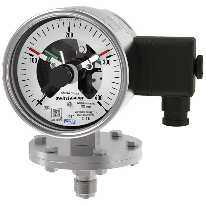
Манометр з діафрагмою та контактами перемикача
Опис
У будь-яких випадках, коли тиск процесу потрібно індикувати локально, а водночас необхідно комутувати кола, застосовується перемикач-манометр моделі PGS43 switchGAUGE.
Контакти перемикача (електричні контакти перемикача) замикають або розмикають електричне коло керування залежно від положення стрілки індикаторного вимірювального приладу. Контакти перемикача регулюються в межах усього діапазону шкали (див. DIN 16085) і встановлюються переважно під циферблатом, хоча також частково — на верхній стороні циферблата. Стрілка приладу (стрілка фактичного значення) вільно переміщується в межах усього діапазону шкали незалежно від встановлення.
Встановлювальну стрілку можна відрегулювати за допомогою знімного регулювального ключа у вікні.
Особливості
- Висока надійність та тривалий термін служби
- Широкий вибір спеціальних матеріалів
- Може використовуватися з наповненням корпуса для високих динамічних навантажень тиском та вібрацій
- Прилади з індуктивними контактами для використання у вибухонебезпечних зонах
- QR-код на шкалі веде до інформації про конкретний прилад
Питання та відповіді
Який діапазон тисків може вимірювати PGS43?
Діапазони шкали — від 0 … 25 мбар до 0 … 25 бар, включно з комбінованими діапазонами (наприклад, −1 … 0 бар) та діапазонами в psi і inHg. Максимальний статичний тиск приладу — до 40 бар.
Наскільки прилад стійкий до перевантаження тиском?
Мембранний манометр PGS43 має запас безпеки від перевантаження до 10-кратного значення повної шкали.
Які варіанти приєднання до процесу доступні?
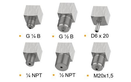
Різьбові з'єднання M20 x 1.5, G 1/2 B, 1/2 NPT, а також відкриті фланцеві з'єднання 1" class 150 RF, 2" class 150 RF, 1" class 300 RF, DN 25 PN 40 та DN 50 PN 40.
З якими середовищами можна використовувати цей манометр?
Придатний для газоподібних і рідких, агресивних, високов'язких та забруднених середовищ. Частини, що омиваються середовищем, можуть бути виготовлені з нержавіючої сталі 316L, сплаву NiCr (Inconel), PTFE, Hastelloy, Monel, танталу чи золота.
У якому температурному діапазоні працює приляд?
Допустима температура навколишнього середовища становить −20 … +70 °C. Дані про температуру середовища в наданих матеріалах не вказані.
Чи є вибухозахищене виконання?
Так, доступні контакти з вибухозахистом ATEX (II 2G Ex ia IIC T6/T5/T4 Gb для газу, II 2D Ex ia IIIB T135 °C Db для пилу) та IECEx, а також схвалення EAC, NEPSI, Ex Ukraine та інших країн.
Який ступінь захисту корпусу?
Корпус має ступінь захисту IP65; можливе заповнення корпусу для високих динамічних навантажень тиском і вібрацій.
Чим відрізняється модель PGS43 від інших контактних манометрів?
Це саме мембранний (діафрагмовий) манометр із контактами перемикача, розрахований на низькі діапазони тиску від 0 … 25 мбар, з 10-кратним запасом безпеки від перевантаження та широким вибором корозійностійких матеріалів частин, що омиваються середовищем.
Зберіть PGS43.1X0 під свою задачу
Артикул збирається автоматично. Якщо сумніваєтесь — напишіть інженеру; підкажемо за параметрами лінії.
- Номінальний розмір100
- перемикачмагнітний кінцевий вимикач миттєвої дії, модель 821
- перше перемиканняmakes (1)
- друга операція перемикачабез
- Вибухозахистбез
- Електричне підключеннябокова частина штекера
- Контактна конструкціябез
- Одиниця зовнішньої шкалиmbar
- Діапазон шкали—
- 2-га шкала або спеціальна шкалабез
- Запобіжний захист від надлишкового тиску5 x значення повної шкали, макс. 40 bar
- Приєднання до процесу—
- Матеріал мембранинержавіюча сталь
- Матеріал нижньої частини корпусуНержавіюча сталь
- Місце підключеннянижнє кріплення
- Рідинне демпфування (заповнення корпусу)—
- Корпус—
- Дросельна шайбабез
- Спеціальні конструктивні особливостібез
Завершіть конфігурацію
Оберіть всі параметри, щоб надіслати запит.
| Модель | PGS43.100 |
| Сімейство | PGS43 |
| Підтип | Diaphragm pressure gauge with switch contacts |
| Діапазон тиску | 0…25 mbar · 0…40 mbar · 0…60 mbar · 0…100 mbar · 0…160 mbar · 0…250 mbar · 0…400 mbar · 0…600 mbar · 0…1000 mbar · 0…0.6 bar · 0…1 bar · 0…1.6 bar · 0…2.5 bar · 0…4 bar · 0…6 bar · 0…10 bar · 0…16 bar · 0…25 bar · 0…30 psi · 0…60 psi · 0…100 psi · 0…150 psi · 0…160 psi · 0…200 psi · 0…250 psi · 0…300 psi · 0…400 psi · 0…10 psi · 0…15 psi · -5…20 mbar · -10…15 mbar · -15…25 mbar · -20…40 mbar · -30…30 mbar · -40…60 mbar · -50…200 mbar · -60…100 mbar · -100…150 mbar · -125…125 mbar · -150…250 mbar · -250…750 mbar · -400…600 mbar · -500…500 mbar · -600…400 mbar · -750…250 mbar · -800…200 mbar · -1…0.6 bar · -1…1 bar · -1…1.5 bar · -1…2 bar · -1…3 bar · -1…5 bar · -1…9 bar · -1…10 bar · -1…15 bar · -1…24 bar · -30…15 inHg · -30…60 inHg · -30…100 inHg · -30…160 inHg · -30…200 inHg · -30…300 inHg · -25…0 mbar · -40…0 mbar · -60…0 mbar · -100…0 mbar · -160…0 mbar · -250…0 mbar · -400…0 mbar · -600…0 mbar · -1000…0 mbar · -0.6…0 bar · -1…0 bar · -15…0 inHg · -30…0 inHg |
| Клас точності | 1.6 |
| Стандарт точності | EN 837-3 |
| Технологічне приєднання | M20 x 1.5Open connecting flange 1" class 150, RFOpen connecting flange 2" class 150, RFOpen connecting flange 1" class 300, RFOpen connecting flange DN 25 PN 40Open connecting flange DN 50 PN 40G ½ B½ NPTG 1/2 B1/2 NPT |
| Вихідний сигнал | Magnetic snap-action contact · Inductive contact · Electronic contact · Reed switch |
| Електр. приєднання | Cable socket M20x1.5 |
| Функція перемикання | Adjustable over full scale range |
| Перемикальні контакти | 4 |
| Матеріал корпусу | Stainless steel 1.4301 (304), Stainless steel 1.4571 (316 Ti) |
| Матеріал змочуваних частин | Stainless steel 316L, NiCr alloy (Inconel), PTFE, Hastelloy, Monel, Tantalum, Gold |
| Матеріал ущільнення | FPM/FKM |
| Темп. навколишнього середовища | −20…+70 °C |
| Ступінь захисту IP | IP65 |
| Сертифікати | CERoHSCRNEN 837-3DIN 16085NACE |
| Вибухозахист | II 2G Ex ia IIC T6/T5/T4 GbII 2D Ex ia IIIB T135°C DbEx ia IIC T6/T5/T4 GbEx ia IIIB T135°C DbATEX directive: Gas II 2G Ex ia IIC T6/T5/T4 Gb, Dust II 2D Ex ia IIIB T135℃ DbIECEx: Gas Ex ia IIC T6/T5/T4 Gb, Dust Ex ia IIIB T135℃ DbEACEx UkraineNEPSIPAC KazakhstanMChSPAC UkrainePAC Uzbekistan |
| Діаметр шкали | 100 mm |
| Мови datasheet | EN |
| Scale range | Overload safety 1) | Vacuum-resist- ant to -1 bar |
|---|---|---|
| mbar | ||
| 0 ... 25 | ■ 125 ■ 250 | Selectable |
| 0 ... 40 | ■ 200 ■ 400 | Selectable |
| 0 ... 60 | ■ 300 ■ 600 | Selectable |
| 0 ... 100 | ■ 500 ■ 1,000 | Selectable |
| 0 ... 160 | ■ 800 ■ 1,600 | Selectable |
| 0 ... 250 | ■ 1,250 ■ 2,500 | Selectable |
| 0 ... 400 | ■ 2,000 ■ 4,000 | Selectable |
| 0 ... 600 | ■ 3,000 ■ 6,000 | Selectable |
| 0 ... 1,000 | ■ 5,000 ■ 10,000 | Selectable |
| bar | ||
| 0 ... 0.6 | ■ 3 ■ 6 | Selectable |
| 0 ... 1 | ■ 5 ■ 10 | Selectable |
| 0 ... 1.6 | ■ 8 ■ 16 | Selectable |
| 0 ... 2.5 | ■ 12.5 ■ 25 | Selectable |
| 0 ... 4 | ■ 20 ■ 40 | Yes |
| 0 ... 6 | ■ 30 ■ 40 | Yes |
| 0 ... 10 | 40 | Yes |
| 0 ... 16 | 40 | Yes |
| 0 ... 25 | 40 | Yes |
| mbar | bar |
|---|---|
| -25 ... 0 | -0.6 ... 0 |
| -40 ... 0 | -1 ... 0 |
| -60 ... 0 | psi |
| -100 ... 0 | -15 inHg ... 0 |
| -160 ... 0 | -30 inHg ... 0 |
| -250 ... 0 | |
| -400 ... 0 | |
| -600 ... 0 | |
| -1,000 ... 0 |
| Scale range | Overload safety 1) | Vacuum-resist- ant to -1 bar | |
|---|---|---|---|
| psi | |||
| 0 ... 10 | ■ 50 ■ 100 | Selectable | |
| 0 ... 15 | ■ 75 ■ 150 | Selectable | |
| 0 ... 30 | ■ 150 ■ 300 | Selectable | |
| 0 ... 60 | ■ 300 ■ 600 | Yes | |
| 0 ... 100 | ■ 500 ■ 1,000 | Yes | |
| 0 ... 150 | ■ 750 ■ 1,500 | Yes | |
| 0 ... 160 | ■ 800 ■ 1,600 | Yes | |
| 0 ... 200 | ■ 1,000 ■ 2,000 | Yes | |
| 0 ... 250 | ■ 1,250 ■ 2,500 | Yes | |
| 0 ... 300 | ■ 1,500 ■ 3,000 | Yes | |
| 0 ... 400 | ■ 2,000 ■ 4,000 | Yes | |
| +/- scale ranges 2) | |||
| Scale range | |||
| mbar | bar | ||
| -5 ...+20 | -1 ... +0.6 | ||
| -10 ...+15 | -1 ...+1 | ||
| -15 ...+25 | -1 ... +1.5 | ||
| -20 ...+40 | -1 ...+2 | ||
| -30 ...+30 | -1 ...+3 | ||
| -40 ...+60 | -1 ...+5 | ||
| -50 ...+200 | -1 ...+9 | ||
| -60 ...+100 | -1 ...+10 | ||
| -100 ...+150 | -1 ...+15 | ||
| -125 ...+125 | -1 ...+24 | ||
| -150 ...+250 | psi | ||
| -250 ...+750 | -30 inHg ...+15 | ||
| -400 ...+600 | -30 inHg ...+60 | ||
| -500 ...+500 | -30 inHg ...+100 | ||
| -600 ...+400 | -30 inHg ...+160 | ||
| -750 ...+250 | -30 inHg ...+200 | ||
| -800 ...+200 | -30 inHg ...+300 |
| Unit | ■ bar ■ psi ■ mbar ■ kg/cm² ■ MPa ■ kPa |
|---|---|
| Other units on request | |
| Overload safety | ■ 5 x full scale value, max. 40 bar ■ 10 x full scale value, max. 40 bar |
| Vacuum resistance | ■ Without ■ Vacuum-resistant to -1 bar |
| Dial | |
| Scale layout | ■ Single scale ■ Dual scale |
| Scale colour | Single scale Black |
| Dual scale Black/Red | |
| Material | Aluminium |
| Customer-specific version | Other scales, e.g. with red mark, circular arcs or circular sectors, on request →Alternatively, adhesive label set for red and green circular arcs; see data sheet AC08.03 |
| Instrument pointer | Aluminium, black |
| Set pointer | Aluminium, red |
Переглянути всі (20)
| Process connection | |
|---|---|
| Standard | ■ EN 837 ■ ANSI / ASME B1.20.1 ■ ASME B16.5 ■ EN 1092-1, form B |
| Size 1) | |
| EN 837 | ■ G½B ■ M20 x 1.5 |
| ANSI / ASME B1.20.1 | ■ ½NPT |
| ASME B16.5 | ■ Open connecting flange 1" class 150, RF ■ Open connecting flange 2" class 150, RF ■ Open connecting flange 1" class 300, RF |
| EN 1092-1, form B | ■ Open connecting flange DN 25 PN 40 ■ Open connecting flange DN 50 PN 40 |
| Materials (wetted) | |
| Diaphragm element | ■ Stainless steel 316L, for span ≤ 0.25 bar ■ NiCr alloy (Inconel), for span > 0.25 bar |
| Process connection with lower measuring flange | Stainless steel 316L |
| Coating / Lining 2) 3) | ■ Without ■ PTFE ■ Hastelloy ■ Monel ■ Tantalum ■ Gold (only for diaphragm element) |
| Other materials on request | |
| Seal 4) | FPM/FKM |
| Output signal | |
|---|---|
| Type of contact | ■ Magnetic snap-action contact, model 821 (→ See page 7) ■ Inductive contact, model 831 (→ See page 8) ■ Electronic contact, model 830 E (→ See page 9) ■ Reed switch, model 851 (→ See page 10) |
| Switching technology | |
| Magnetic snap-action contact, model 821 | ■ No control unit and no supply voltage required ■ Direct switching up to 250 V, 1 A |
| Inductive contact, model 831 | ■ Suitable for use in hazardous areas with corresponding control unit (model 904.xx) ■ Long service life due to non-contact sensor ■ Low influence on the indication accuracy ■ Fail-safe switching at high switching frequency ■ Insensitive to corrosion ■ Also available in safety version |
| Electronic contact, model 830 E | ■ For direct triggering of a programmable logic controller (PLC) ■ Long service life due to non-contact sensor ■ Low influence on the indication accuracy ■ Fail-safe switching at high switching frequency ■ Insensitive to corrosion |
| Reed switch, model 851 | ■ No control unit and no supply voltage required ■ Direct switching up to 250 V, 1 A ■ For direct triggering of a programmable logic controller (PLC) ■ Free from wear as without contact |
| Contact setting | ■ Contact(s) adjustable, adjustment key attached to cable socket ■ Contact(s) fixed, without adjustment lock 1) ■ Adjustment lock sealable (tamper-proof) ■ Adjustment lock sealed (tamper-proof) 1) ■ Captive adjustment key with the adjustment lock connected |
| Type of contact | Magnetic snap-action contact |
|---|---|
| Switching technology | ■ No control unit and no supply voltage required ■ Direct switching up to 250 V, 1 A |
| Number of switch contacts | |
| Span ≥ 25 mbar ...< 40 mbar 1) | Max. 2 switch contacts |
| Span ≥ 40 mbar | Max. 4 switch contacts |
| Switching function | ■ Separate circuits with ≥ 2 switches ■ Cable break monitoring with parallel resistance (47 kΩ or 100 kΩ) |
| The switching function of each switch is indicated by index 1, 2 or 3 | |
| Model 821.1 | Normally open (clockwise pointer motion) |
| Model 821.2 | Normally closed (clockwise pointer motion) |
| Model 821.3 | Change-over; one contact breaks and one contact makes simultaneously when pointer reaches set point |
| Switch point setting | Set pointers of the contact pressure gauges are freely adjustable over the full scale range |
| Setting range (recommended) | 25 ... 75 %of span (0 ... 100 %onrequest) |
| Distance between switch points | Recommended minimum distance between 2 contacts: 20 %of span |
| Switch hysteresis | 2 ... 5 %(typical) |
| Switching current | 0.02 ... 0.3 A (resistive load) Permissible switch-on and switch-off current: ≤ 0.5 A |
| Switching voltage | AC/DC 24 ...250V |
| Switching power 2) | |
| Unfilled instruments | ≤ 30 W, ≤ 50VA |
| Filled instruments | ≤ 20 W, ≤ 20VA |
| Contact material | Silver-nickel, gold-plated |
| Switching voltage | Unfilled instruments | Filled instruments | ||||
|---|---|---|---|---|---|---|
| Resistive load | Inductive load | Resistive load | Inductive load | |||
| Direct current | Alternating current | cos ϕ>0.7 | Direct current | Alternating current | cos ϕ>0.7 | |
| DC 220 V / AC 230 V | 100mA | 120mA | 65mA | 65mA | 90mA | 40mA |
| DC 110 V / AC 110 V | 200mA | 240mA | 130mA | 130mA | 180mA | 85mA |
| DC 48 V / AC 48 V | 300mA | 450mA | 200mA | 190mA | 330mA | 130mA |
| DC 24 V / AC 24 V | 400mA | 600mA | 250mA | 250mA | 450mA | 150mA |
| Type of contact | Inductive contact |
|---|---|
| Switching technology | ■ Suitable for use in hazardous areas with corresponding control unit (model 904.xx) ■ Long service life due to non-contact sensor ■ Low influence on the indication accuracy ■ Fail-safe switching at high switching frequency ■ Insensitive to corrosion ■ Also available in safety version |
| Number of switch contacts | |
| Span ≥ 25 mbar 1) | Max. 3 switch contacts |
| Switching function | Contact versions: ■ 831-N ■ 831-SN, safety version 2) ■ 831-S1N, safety version 2) , inverted signal The switching function of each switch is indicated by index 1 or 2 |
| Model 831.1 | Normally open (clockwise pointer motion) |
| Model 831.2 | Normally closed (clockwise pointer motion) |
| Switch point setting | Set pointers of the contact pressure gauges are freely adjustable over the full scale range |
| Setting range (recommended) | 10 ... 90 %of span (0 ... 100 %onrequest) |
| Distance between switch points | Up to 2 contacts can be set to an identical set point. For a version with 3 contacts this is not possible.The left (no. 1) or right (no. 3) contact may not be set to the same set point as the other 2 contacts.The required displacement is approx. 30°, optionally to the right or to the left. |
| Switching current | Depending on the control unit used (→ See data sheet AC 08.04) |
| Switching voltage | Depending on the control unit used (→ See data sheet AC 08.04) |
| Switching power | Depending on the control unit used (→ See data sheet AC 08.04) |
| Permissible temperature ranges in hazardous areas | |
| T6 | -20 ...+60 °C |
| T5 ...T1 | -20 ...+70 °C |
| T135°C | -20 ...+70 °C |
| Model | Version | Ex version |
|---|---|---|
| 904.28 KFA6 - SR2 - Ex1.W | 1 contact | Yes |
| 904.29 KFA6 - SR2 - Ex2.W | 2 contacts | Yes |
| 904.30 KHA6 - SH - Ex1 | 1 contact | Yes - Safety version |
| 904.33 KFD2 - SH - Ex1 | 1 contact | Yes - Safety version |
| 904.25 MSR 010-I | 1 contact | No |
| 904.26 MSR 020-I | 2 contacts | No |
| 904.27 MSR 011-I | Two-point control | No |
| Type of contact | Electronic contact (PNP transistor) |
|---|---|
| Switching technology | ■ For direct triggering of a programmable logic controller (PLC) ■ Long service life due to non-contact sensor ■ Low influence on the indication accuracy ■ Fail-safe switching at high switching frequency ■ Insensitive to corrosion |
| Number of switch contacts | |
| Span ≥ 25 mbar 1) | Max. 3 switch contacts |
| Switching function | Contact versions: ■ 2-wire system ■ 3-wire system |
| The switching function of each switch is indicated by index 1 or 2 | |
| Model 830 E.1 | Normally open (clockwise pointer motion) |
| Model 830 E.2 | Normally closed (clockwise pointer motion) |
| Setting range (recommended) | 10 ... 90 %of span (0 ... 100 %onrequest) |
| Distance between switch points | Up to 2 contacts can be set to an identical set point. For a version with 3 contacts this is not possible.The left (no. 1) or right (no. 3) contact may not be set to the same set point as the other 2 contacts.The required displacement is approx. 30°, optionally to the right or to the left. |
| Switching current | ≤ 100mA |
| Switching voltage | DC 10 ...30V |
| Type of contact 1) 2) | Bistable reed switch |
|---|---|
| Switching technology | ■ No control unit and no supply voltage required ■ Direct switching up to 250 V, 1 A ■ For direct triggering of a programmable logic controller (PLC) ■ Free from wear as without contact |
| Number of switch contacts | |
| NS 100 [4"] | Max. 2 switch contacts |
| NS 160 [6"] 3) | 1 switch contact |
| Switching function | ■ Separate circuits with ≥ 2 switches ■ Cable break monitoring with parallel resistance (47 kΩ or 100 kΩ) |
| The switching function of each switch is indicated by index 1, 2 or 3 | |
| Model 851.1 | Normally open (clockwise pointer motion) |
| Model 851.2 | Normally closed (clockwise pointer motion) |
| Model 851.3 | Change-over; one contact breaks and one contact makes simultaneously when pointer reaches set point |
| Switch point setting | Set pointers of the contact pressure gauges are freely adjustable over the full scale range |
| Setting range (recommended) | 10 ... 90 %of span |
| Distance between switch points | When using two contacts, these cannot be set to the same point. Depending on the switch- ing function, a minimum clearance of 15 ... 30° is required. |
| Switch hysteresis | 3 ...5% |
| Switching current | ≤ AC/DC 1 A |
| Switching voltage | ≤ AC/DC 250V |
| Switching power | ≤ 60 W, 60VA |
| Contact material | Rhodium |
| Transport current | AC/DC 2 A |
| Inductive load cosϕ | 1 |
| Contact resistance (static) | 100mΩ |
| Insulation resistance | 109Ω |
| Breakdown voltage | DC 1,000V |
| Switching time incl. contact chatter | 4.5 ms |
| Connection type | ■ Cable socket, black PerVDE 0110 insulation group C/250V Cable gland M20 x 1.5 ■ Connector (instead of cable socket) |
|---|---|
| Wire cross-section | 6 screw terminals + PE for 2.5 mm² |
| Cable diameter | →See dimensions |
| Pin assignment | Connection details are given on the product label of the instrument. Connection termi- nals and ground terminals are appropriately marked. |
| Material | PA 6 (polyamide) |
| Medium temperature range | ■ +100 °C [+212 °F] maximum ■ +200 °C [+392 °F] maximum |
|---|---|
| Ambient temperature range | -20 ...+60 °C [-4 ... 140 °F] |
| Storage temperature range | -20 ...+60 °C [-4 ... 140 °F] |
| Pressure limitation | |
| Steady | Full scale value |
| Fluctuating | 0.9 x full scale value |
| Ingress protection per IEC/EN 60529 | ■ IP54 ■ IP65 1) ■ IP66 2) (ingress protection of the case) |
| Logo | Description | Region |
|---|---|---|
| EU | declaration of conformity | European Union |
| EMCdirective | ||
| Low voltage directive | directive | |
| RoHS - | CRN Safety (e.g. electr. safety, overpressure, ...) | Canada |
| Logo | Description | Region |
|---|---|---|
| EU declaration of conformity | European Union | |
| ATEX directive 1) Hazardous areas IECEx 1) | International | |
| EAC EMCdirective | Eurasian Economic Community | |
| Ex Ukraine Hazardous areas 1) | Ukraine | |
| NEPSI Hazardous areas 1) | China | |
| PAC Kazakhstan Metrology, measurement technology | Kazakhstan | |
| - | MChS Permission for commissioning | Kazakhstan |
| PAC Ukraine Metrology, measurement technology | Ukraine | |
| PAC Uzbekistan Metrology, measurement technology | Uzbekistan |
| Certificates | ■ 2.2 test report per EN 10204 (e.g. state-of-the-art manufacturing, indication accuracy) ■ 3.1 inspection certificate per EN 10204 (e.g. indication accuracy) |
|---|---|
| Recommended calibration interval | 1 year (dependent on conditions of use) |
| Process connection G | Scale range | Dimensions inmm | ||||||
|---|---|---|---|---|---|---|---|---|
| Ø d | h | S2 | S3 | S4 | S5 | S6 | ||
| G½B | ≤ 250 mbar | 160 | 119 | Ø6 | 20 | 3 | 17 | Ø17.5 |
| G½B | > 250 mbar | 100 | 117 | Ø6 | 20 | 3 | 17 | Ø17.5 |
| ½NPT | ≤ 250 mbar | 160 | 118 | - | 19 | - | - | - |
| ½NPT | > 250 mbar | 100 | 116 | - | 19 | - | - | - |
| Type of contact | Dimensions inmm | |
|---|---|---|
| X | Y | |
| Single or double contact | 88 | 55 |
| Double (change-over) contact | 113 | 80 |
| Triple contact | 96 | 63 |
| Quadruple contact | 113 | 80 |
| Process connection G | Scale range | Dimensions inmm | ||||||
|---|---|---|---|---|---|---|---|---|
| Ø d | h | S2 | S3 | S4 | S5 | S6 | ||
| G½B | ≤ 250 mbar | 160 | 119 | Ø6 | 20 | 3 | 17 | Ø17.5 |
| G½B | > 250 mbar | 100 | 117 | Ø6 | 20 | 3 | 17 | Ø17.5 |
| ½NPT | ≤ 250 mbar | 160 | 118 | - | 19 | - | - | - |
| ½NPT | > 250 mbar | 100 | 116 | - | 19 | - | - | - |
Не знайшли відповіді у документації? Інженер відповість впродовж робочого дня.
Запитати інженера →149 стандартних артикулів сімейства PGS43
Якщо знаєте код — оберіть напряму. Якщо ні — користуйтесь конфігуратором у режимі «01».