
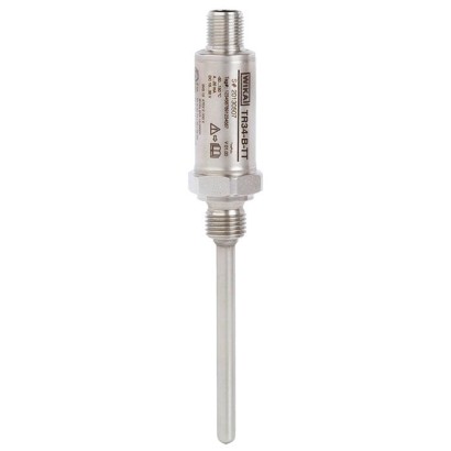
מדחום התנגדות מיניאטורי
תיאור
מדחומי התנגדות מסדרות אלה משמשים כמדחומים אוניברסליים למדידת טמפרטורה של נוזלים וגזים בטווח -50 ... +250 °C [-58 ... +482 °F]. המכשירים הם בעלי בטיחות מהותית ומתאימים לשימוש באזורים מסוכנים.
ניתן להשתמש בהם ללחצים עד 140 bar [2,030 psi] עם קטרי חיישן של 3 mm [0.12 in] ועד 270 bar [3,916 psi] עם קטרי חיישן של 6 mm [0.24 in], בהתאם לגרסת המכשיר. כל הרכיבים החשמליים מוגנים מפני לחות (IP67 או IP69K) ומיועדים לעמוד בפני רטט (20 g, בהתאם לגרסת המכשיר).
מדחום ההתנגדות זמין עם יציאת חיישן ישירה או עם משדר משולב, שניתן להגדיר באופן פרטני באמצעות תוכנת התצורה למחשב WIKAsoft-TT. ניתן להתאים טווח מדידה, דהייה, איתות שגיאה בהתאם ל-NAMUR NE 043 ומספר TAG no.
לאישורים נוספים, ראה עמוד 8
תכונות מיוחדות
- גרסה בטוחה פנימית Ex i, תכנון קומפקטי מאוד, עמידות גבוהה לרעידות וזמן תגובה מהיר
- עם מוצא חיישן ישיר (Pt100, Pt1000 בחיבור 2-, 3- או 4-חוטי) או משדר מובנה עם אות פלט 4 ... 20 mA
- משדר משולב הניתן לפרמטור באופן עצמאי באמצעות תוכנת ההגדרה WIKAsoft-TT למחשב, ללא עלות
- אלמנט חיישן בדיוק מחלקה A לפי IEC 60751
שאלות ותשובות
מהו טווח המדידה של מדחום ה-TR34?
טווח טמפרטורת התהליך הוא -50 … +250 °C, בהתאם לגרסת המכשיר.
מהי הדיוק של המדחום?
המשדר המשולב מספק דיוק של ±0.25 K, ורכיב החיישן עומד במחלקת דיוק A לפי IEC 60751.
אילו חיבורי תהליך זמינים?
זמינים חיבורים מוברגים: G¼B, G⅜B, G½B, ¼NPT, ½NPT, M12 x 1.5, M20 x 1.5 ו-7/16-20 UNF-2A.
האם המדחום מתאים למדיומים נוזליים וגזיים?
כן, ה-TR34 משמש למדידת טמפרטורה של נוזלים וגזים בטווח -50 … +250 °C.
מהו טווח הטמפרטורה הסביבתית?
המדחום מיועד לפעולה בטמפרטורה סביבתית של -40 … +85 °C.
מהי דרגת ההגנה מפני חדירה?
כל הרכיבים החשמליים מוגנים מפני לחות בדרגת IP67.
האם המדחום מאושר לשימוש באזורים מסוכנים?
כן, ה-TR34 זמין בגרסה בבטיחות מהותית Ex i, המתאימה לשימוש באזורים מסוכנים.
מה מבדיל את ה-TR34 מדגמים אחרים בסדרה?
ה-TR34 הוא הגרסה המוברגת והמוגנת מפני פיצוץ: עיצוב מיניאטורי עם קוטר מדחום של 3 mm, חיישן מפלדת אל-חלד 1.4571, ובחירה בין יציאת חיישן ישירה למשדר משולב עם HART הניתן לתצור באמצעות WIKAsoft-TT.
| דגם | TR34 |
| תת-קטגוריה | Resistance thermometer with integrated transmitter or direct output |
| טווח טמפרטורה | −50…+250 °C · −30…+150 °C · −20…+125 °C |
| מחלקת דיוק | ±0.25 K (transmitter), Class A (sensor) |
| חיבור תהליך | G¼BG⅜BG½B¼NPT½NPTM12 x 1.5M20 x 1.57/16-20 UNF-2A |
| טמפ׳ תהליך | −50…+250 °C |
| אות יציאה | 4-20mA · HART |
| הזנה | DC 10 ... 30V |
| חיבור חשמלי | M12 x 1 circular connector (4-pin) |
| חומר גשש | Stainless steel 1.4571 |
| טמפ׳ סביבה | −40…+85 °C |
| דרגת הגנה IP | IP67 |
| תקנים | CEEACRoHSREACH |
| הגנת התפוצצות | Ex i |
| סוג חיישן | Pt100, Pt1000 |
| מחלקת חיישן | A, B |
| קוטר גשש | 3 mm |
| תרמופור | לא |
| שפות גיליון נתונים | EN, DE |
| Type of measuring element | ||
|---|---|---|
| Version 4 ... 20 mA(modelTR34-x-TT) | Pt1000 (measuring current < 0.3 mA;self-heating can be ignored) | |
| Version Pt100 (model TR34-x-Px) / Pt1000 (model TR34-x-Sx) | ■ Pt100 (measuring current: 0.1 ... 1.0 mA) ■ Pt1000 (measuring current: 0.1 ... 0.3 mA) | |
| → For detailed specifications for Pt sensors, see Technical information IN 00.17 at www.wika.com. | ||
| Connection method | ||
| Version 4 ... 20 mA(modelTR34-x-TT) | 2-wire | |
| Version Pt100 (model TR34-x-Px) / Pt1000 (model TR34-x-Sx) | 2-wire | The lead resistance is recorded as an error in the measurement |
| 3-wire | With a cable length of 30 mor longer, measuring deviations can occur | |
| 4-wire | The lead resistance can be ignored | |
| Tolerance value of the measuring element 1) per IEC 60751 | ||
| Version 4 ... 20 mA(modelTR34-x-TT) | Class A | |
| Version Pt100 (model TR34-x-Px) / Pt1000 (model TR34-x-Sx) | ■ Class A ■ Class B at | 2-wire |
| Tolerance value of the measuring element 1) per IEC 60751 | Class A |
|---|---|
| Measuring deviation of the transmitter per IEC 62828 | ±0.25 K |
| Total measuring deviation per IEC 62828 | Measuring deviation of the measuring element + transmitter |
| Influence of ambient temperature | 0.1 %of the set measuring span / 10 KT a |
| Influence of supply voltage | ±0.025 %/V(depending on the supply voltage U B ) |
| Influence of load | ±0.05 %/ 100Ω |
| Linearisation | Linear to temperature per IEC 60751 |
| Output error | ±0.1% 2) |
| Reference conditions | |
| Ambient temperatureT a ref | 23 °C |
| Supply voltage U B ref | DC 12V |
| Temperature range | ||
|---|---|---|
| Version 4 ... 20 mA(modelTR34-x-TT) | Without neck tube -30 ...+150 °C [-22 ...+302 °F] With neck tube -30 ...+250 °C [-22 ...+482 °F] 1) Version with FKM O-ring: -20 ...+125 °C [-4 ...+257 °F] | |
| Version Pt100 (model TR34-x-Px) / Pt1000 (model TR34-x-Sx) | Class A | Without neck tube -30 ...+150 °C [-22 ...+302 °F] With neck tube -30 ...+250 °C [-22 ...+482 °F] Version with FKM O-ring: -20 ...+125 °C [-4 ...+257 °F] |
| Class B | Without neck tube -50 ...+150 °C [-58 ...+302 °F] With neck tube -50 ...+250 °C [-58 ...+482 °F] | |
| Unit (4 ... 20 mA version) | Configurable °C, °F, K | |
| Temperature at the connector (Pt100, Pt1000 version) | Max. 85 °C [185 °F] | |
| Measuring span (4 ... 20 mA version) | Minimum 20 K, maximum 300 K |
| Process connection | |
|---|---|
| Type of process connection | ■ G¼B ■ G⅜B ■ G½B ■ ¼NPT ■ ½NPT ■ M12 x 1.5 ■ M20 x 1.5 ■ 7/16-20 UNF-2A |
| Protection tube | |
| Protection tube diameter | ■ 3 mm[0.12 in] ■ 6 mm[0.24 in] |
| Insertion length U 1 | ■ 50 mm[1.97 in] ■ 75 mm[2.95 in] 1) ■ 100 mm[3.94 in] 1) ■ 120 mm[4.72 in] 1) ■ 150 mm[5.91 in] 1) ■ 200 mm[7.87 in] 1) ■ 250 mm[9.84 in] 1) ■ 300 mm[11.81 in] 1) ■ 350 mm[13.78 in] 1) ■ 400 mm[15.75 in] 1) Other insertion lengths on |
| request | |
| Material (wetted) | Stainless steel 1.4571 |
הצגת הכול (20)
| Output signal (4 ... 20 mA version) | |
|---|---|
| Analogue output | 4 ... 20 mA, 2-wire |
| Load R A | R A ≤ (U B - 10 V) / 23 mAwith R A in Ωand U B inV The permissible load depends on the loop supply voltage. For communication with the instrument with programming unit PU-548, a max. load of 350 Ωis admissible. |
| Load diagram | Load R A inΩ Voltage U B inV 0 10 24 30 833 583 |
| Factory configuration | |
| Measuring range | Measuring range 0 ... 150 °C [32 ... 302 °F] Other measuring ranges are adjustable |
| Current values for error signalling | Configurable in accordance with NAMUR NE 043 downscale ≤ 3.6mA upscale ≥ 21.0mA |
| Current value for sensor short-circuit | Not configurable in accordance with NAMUR NE 043 downscale ≤ 3.6mA |
| Communication | |
| Info data | TAG no., description and user message can be stored in transmitter |
| Configuration and calibration data | Permanently stored |
| Configuration software | WIKAsoft-TT → Configuration software (multilingual) as a download from www.wika.com |
| Voltage supply | |
| Supply voltage U B | DC 10 ...30V |
| Supply voltage input | Protected against reverse polarity |
| Permissible residual ripple of supply voltage | 10 %generated by U B < 3 %ripple of the output current |
| Time response | |
| Switch-on delay, electrical | Max. 4 s (time before the first measured value) |
| Warm-up time | After approx. 4 minutes, the instrument will function to the specifications (accuracy) given in the data sheet. |
| Sensor current | < 0.3 mA(self-heating can be ignored) |
| Connection type | M12 x 1 circular connector (4-pin) |
|---|---|
| Material | Stainless steel 1.4571 |
| Pin | Signal | Description |
|---|---|---|
| 1 | L+ | 10 ...30V |
| 2 | VQ | not connected |
| 3 | L- | 0V |
| 4 | C | not connected |
| Operating conditions | |
|---|---|
| Ambient temperature range | |
| Version 4 ... 20 mA(modelTR34-x-TT) | -40 ...+85 °C [-40 ...+185 °F] Version with FKM O-ring: -20 °C [-4 °F] |
| Version Pt100 (model TR34-x-Px) / Pt1000 (model TR34-x-Sx) | -50 ...+85 °C [-58 ...+185 °F] Version with FKM O-ring: -20 °C [-4 °F] |
| Storage temperature range | -40 ...+85 °C [-40 ...+185 °F] Version with FKM O-ring: -20 °C [-4 °F] |
| Climate class per IEC 60654-1 | |
| Version 4 ... 20 mA(modelTR34-x-TT) | Cx (-40 ...+85 °C [-40 ...+185 °F], 5 ... 95 %r.h.) Version with FKM O-ring: -20 °C [-4 °F] |
| Version Pt100 (model TR34-x-Px) / Pt1000 (model TR34-x-Sx) | Cx (-50 ...+85 °C [-58 ...+185 °F], 5 ... 95 %r.h.) Version with FKM O-ring: -20 °C [-4 °F] |
| Maximum permissible humidity, condensation | 100 %r.h., condensation allowed |
| Maximum operating pressure 1) 2) | |
| With sensor diameter 3 mm[0.12 in] | 140 bar [2,030 psi] |
| With sensor diameter 6 mm[0.24 in] | 270 bar [3,916 psi] |
| Salt fog | IEC 60068-2-11 |
| Vibration resistance per IEC 60751 | 10 ... 2,000 Hz, 20 g 1) |
| Shock resistance per IEC 60068-2-27 | 50 g, 6 ms, 3 axes, 3 directions, three times per direction |
| Ingress protection (IP code) | |
| Case with connected connector | ■ IP67 per IEC/EN 60529 ■ IP69 per IEC/EN 60529 ■ IP69K per ISO 20653 |
| The stated ingress protection only applies when plugged in using line connectors that have the appropriate ingress protection. | |
| Coupler connector, not connected | IP67 per IEC/EN 60529 |
| Weight | Approx. 0.2 ... 0.7 kg [0.44 ... 1.54 lbs] - depending on version |
| Material | Stainless steel |
| Hazardous gas atmosphere | Temperature class | Ambient temperature range (T a ) | Maximum surface temperature (T max ) at the tip of the probe or protection tube |
|---|---|---|---|
| II 1G Ex ia IIC T1 - T6 Ga II 1/2G Ex ia IIC T1 - T6 Ga/Gb II 2G Ex ia IIC T1 - T6 Gb | T6 | -40 ...+45 °C | T M (medium temperature) + self-heating (15 K) Pay attention to the special conditions for safe |
| T5 | -40 ...+60 °C | use. | |
| T4 | -40 ...+85 °C | ||
| T3 | -40 ...+85 °C | ||
| T2 | -40 ...+85 °C | ||
| T1 | -40 ...+85 °C |
| Hazardous dust/air atmospheres | Power P i | Ambient temperature range (T a ) | Maximum surface temperature (T max ) at the tip of the probe or protection tube |
|---|---|---|---|
| II 1D Ex ia IIIC T135 °C Da II 1/2D Ex ia IIIC T135 °C Da/Db II 2D Ex ia IIIC T135 °C Db | 750mW 650mW 550mW | -40 ...+40 °C -40 ...+70 °C -40 ...+85 °C | T M (medium temperature) + self-heating (15 K) Pay attention to the special conditions for safe use. |
| Parameters | Hazardous gas atmosphere | Hazardous dust/air atmospheres |
|---|---|---|
| Terminals | + / - | + / - |
| Voltage U i | DC 30V | DC 30V |
| Current l i | 120mA | 120mA |
| Power P i | 800mW | 750/650/550mW |
| Effective internal capacitance C i | 29.7 nF | 29.7 nF |
| Effective internal inductance L i | Negligible | Negligible |
| Maximum self-heating at the probe or protection tube tip | 15 K | 15 K |
| Marking | Temperature class | Ambient temperature range (T a ) | Maximum surface temperature (T max ) at the tip of the probe or protection tube |
|---|---|---|---|
| II 1G Ex ia IIC T1 - T6 Ga II 1/2G Ex ia IIC T1 - T6 Ga/Gb II 2G Ex ia IIC T1 - T6 Gb | T6 | -50 ...+80 °C -50 ...+85 °C | T M (medium temperature) + self-heating Pay attention to the special conditions for safe use. |
| T5 | |||
| T4 | -50 ...+85 °C | ||
| T3 | -50 ...+85 °C | ||
| T2 | -50 ...+85 °C | ||
| T1 | -50 ...+85 °C |
| Marking | Power P i | Ambient temperature range (T a ) | Maximum surface temperature (T max ) at the tip of the probe or protection tube |
|---|---|---|---|
| II 1D Ex ia IIICT135 °C Da II 1/2D Ex ia IIIC T135 °C Da/Db II 2D Ex ia IIIC T135 °C Db | 750mW 650mW 550mW | -50 ...+40 °C -50 ...+70 °C -50 ...+85 °C | T M (medium temperature) + self-heating Pay attention to the special conditions for safe use. |
| Parameters | Gas applications | Dust applications |
|---|---|---|
| Terminals | 1 - 4 | 1 - 4 |
| Voltage U i | DC 30V | DC 30V |
| Current l i | 550mA | 250mA |
| Power P i | 1,500mW | 750/650/550mW |
| Effective internal capacitance C i | Negligible | Negligible |
| Effective internal inductance L i | Negligible | Negligible |
| Maximum self-heating at the probe or protection tube tip | (R th ) = 335 K/W | (R th ) = 335 K/W |
| Logo | Description | Region |
|---|---|---|
| EU declaration of | conformity | European Union |
| EMCdirective 1) EN 61326 emission (group 1, | class B) and immunity (industrial application) | |
| ATEX - Ex i | directive Hazardous areas Zone 0 gas II 1G Ex ia IIC T1 ...T6 Ga Zone 1 mounting to zone 0 gas II 1/2G Ex ia IIC T1 ...T6 Ga/Gb |
| Logo | Description | Region | |
|---|---|---|---|
| IECEx - in combination with ATEX Hazardous areas | International | ||
| CSA | USA and Canada | ||
| Safety (e.g. electr. safety, overpressure, ...) | |||
| Hazardous areas - Ex i (for Canada) Division Division Division Division Zone Zone Zone Zone - Ex i (for USA) Division Division Division Division Zone Zone Zone | CL I, DIV 1, GP A, B, C, D, T1 ...T6 CL I, DIV 2, GP A, B, C, D, T1 ...T6 CL II / III, DIV 1, GP E, F, G, T135 °C CL II / III, DIV 2, GP E, F, G, T135 °C Ex ia IICT1…T6 Ga Ex ia IICT1…T6Gb Ex ia IIIC T135 °C Da Ex ia IIIC T135 °C Db CL I, DIV 1, GP A, B, C, D, T1 ...T6 CL I, DIV 2, GP A, B, C, D, T1 ...T6 CL II / III, DIV 1, GP E, F, G, T135 °C CL II / III, DIV 2, GP E, F, G, T135 °C CL I, zone 0, IIC AEX ia T1 ...T6 Ga CL I, zone 1, IIC AEX ia T1 ...T6 Gb CL II, zone 20, IIIC AEX ia T135 °C Da | ||
| EAC | Eurasian Economic Community | ||
| EMCdirective 1) | |||
| Hazardous areas - Ex i Zone 0 gas 0 Ex ia IICT6…T1GaX Zone 1 gas 1 Ex ia IICT6…T1GbX Zone 20 dust Ex ia IIIC 135 °C Da X Zone 21 dust Ex ia IIIC 135 °C Db X |
| Logo | Description | Region |
|---|---|---|
| Ex Ukraine Hazardous areas - Ex i Zone 1 gas Ex ia IIC T1 ...T6 Gb Zone 0 gas Ex ia IIC T3 ...T6 Ga | Ukraine | |
| CCC 1) Hazardous areas - Ex i Zone 1 gas Ex ia IIC T3 ...T6 Gb Zone 1 mounting to zone 0 gas Ex ia IIC T3 ...T6 Ga/Gb - Ex n Zone 2 gas Ex nA IIC T1 ...T6 | China | |
| DNOP - MakNII Mining | Ukraine | |
| PAC Russia Metrology, measurement technology | Russia | |
| PAC Kazakhstan Metrology, measurement technology | Kazakhstan | |
| - | MChS Permission for commissioning | Kazakhstan |
| PAC Belarus Metrology, measurement technology | Belarus | |
| - | PAC Ukraine Metrology, measurement technology | Ukraine |
| PAC Uzbekistan Metrology, measurement technology | Uzbekistan |
| Certification type | Measurement accuracy | Material certificate |
|---|---|---|
| 2.2 test report | x | x |
| 3.1 inspection certificate | x | x |
| DAkkS calibration certificate | x | - |
| Model | Description | Order no. | |
|---|---|---|---|
| Programming unit Model PU-548 | ■ Easy to use ■ LED status display ■ Compact design ■ No further voltage supply needed, neither for the programming unit nor for the transmitter | 14231581 | |
| Adapter cable | (replaces programming unit model PU-448) Adapter cable for the connection of a modelTR34 resistance thermometer to the model PU-548 programming unit | 14003193 | |
| M12 x 1 transmitter adapter to DIN EN 175301-803 angular connector (yellow female connector element) | Adapter for the connection of a resistance thermometer with a DIN EN 175301-803 angular connector form A with a 4 ...20mA output signal → see data sheet AC 80.17 Case: PA Ambient temperature: -40 ...+115 °C [-40 ...+239 °F] Union nut: Zinc die-cast Contacts: Copper-zinc alloy, tin-plated Dielectric strength: 500V Ingress protection: IP65 4 ...20mA M12 x 1 connector Angular connector | 14069503 | |
| M12 x 1 Pt adapter to DIN EN 175301-803 angular connector (black female connector element) | Adapter for the connection of the resistance thermometer with a DIN EN 175301-803 form A angular connector with direct resistance output signal → see data sheet AC 80.17 Case: PA Ambient temperature: -40 ...+115 °C [-40 ...+239 °F] Union nut: Zinc die-cast Contacts: Copper-zinc alloy, tin-plated Dielectric strength: 500V 4 ...20mA | 14061115 | |
| Angular connector | Per DIN EN 175301-803 form A | 11427567 | |
| Sealing for angular connector | For use with angular connector DIN EN 175301-803-A EPDM, brown | 11437902 |
| Model | Description | Order no. | ||
|---|---|---|---|---|
| - | M12 connection cable | Cable socket straight, 4-pin, ingress protection IP67 Temperature range -20 ...+80 °C [-4 ...+176 °F] | Cable length2m [6.56 ft] | 14086880 |
| Cable length5m [16.40 ft] | 14086883 | |||
| Angled socket, 4-pin, ingress protection IP67 Temperature range -20 ...+80 °C [-4 ...+176 °F] | Cable length2m [6.56 ft] | 14086889 | ||
| Cable length5m [16.40 ft] | 14086891 | |||
| - | M12 connector | Female angled, 4-pin, ingress protection IP67 Screw connection for conductor cross-section 0.25…0.75mm² [24…18AWG] Cable gland Pg7, outside diameter of cable 4 …6mm[0.16 Temperature range -40 ...+80 °C [-40 ...+176 °F] | ... 0.24 in] | 14136815 |
לא מצאתם תשובה בתיעוד? מהנדס יענה במהלך יום עסקים.
שאלו מהנדס →80 מק״טים סטנדרטיים של משפחת TR34
אם ידוע הקוד — בחרו ישירות. אם לא — השתמשו בתצורה במצב «01».