
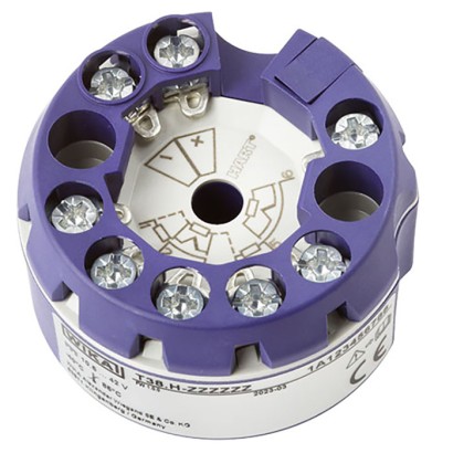
משדר טמפרטורה דיגיטלי
תיאור
משדרי הטמפרטורה הללו מיועדים לשימוש אוניברסלי בתעשיית התהליכים. הם מספקים דיוק גבוה באמצעות התאמת חיישן-משדר, אמינות מרבית והגנה מצוינת מפני השפעות אלקטרומגנטיות. באמצעות פרוטוקול HART ®, ניתן להגדיר את משדרי הטמפרטורה מדגם T38 (תואמים) באמצעות מגוון כלי תצורה פתוחים. בנוסף, ניתן לפרמטר את משדרי הטמפרטורה מדגם T38, באמצעות תוכנת התצורה WIKAsoftTT עם יחידת תכנות מדגם PU-548, בצורה קלה מאוד, מהירה ובתצוגה ברורה.
בנוסף לבחירת סוג החיישן וטווח המדידה, התוכנה מאפשרת לשמור פעולת איתות שגיאות, דיכוי (damping), מספר תיאורי נקודות מדידה והתאמה לתהליך.
תכונות מיוחדות
- גרסת SIL מאושרת TÜV בהתאם ל-IEC 61508 (אופציה)
- פעולה ביישומי בטיחות עד SIL 2/SIL 3
- ניתן להגדרה עם כמעט כל כלי ההגדרה
- אוניברסלי לחיבור של 1 או 2 חיישנים: מדחום התנגדות (עד 2 x 3-חוט), צמד תרמי, חיישן מתח, פוטנציומטר, שרשראות Reed ואחרים
- איתות בהתאם ל-NAMUR NE43, ניטור חיישן בהתאם ל-NE89, EMC בהתאם ל-NE21, ניטור עצמי ואבחון של מכשירי שדה בהתאם ל-NE107
שאלות ותשובות
מהו טווח המדידה של ה-T38?
הטווח תלוי בסוג החיישן המחובר; הטווחים הנתמכים משתרעים מ--270 °C ועד +2500 °C.
מהו הדיוק של המשדר?
±(0.06 K + 0.015 % MV) עבור Pt100, ±(0.1 K + 0.04 % MV) עבור Type K; הדיוק משתנה לפי סוג החיישן.
אילו סוגי חיישנים ניתן לחבר?
Pt100, Pt1000, JPt100, JPt1000, Ni100, צמדים תרמיים מסוג J, K, L, E, N, T, U, R, S, B, C, A, חיישני mV, פוטנציומטרים ושרשראות Reed. ניתן לחבר חיישן אחד או שניים (עד 2 x 3-חוט).
מהו אות הפלט והפרוטוקול?
המשדר פולט 4-20 mA עם פרוטוקול HART®.
מהן טמפרטורות הסביבה המותרות?
המשדר פועל בטמפרטורת סביבה של -40 … +85 °C.
מהי דרגת ההגנה מפני חדירה?
דרגת ההגנה היא IP65.
האם המשדר מתאים ליישומי בטיחות (SIL)?
כן. קיימת גרסת SIL מאושרת TÜV לפי IEC 61508 (אופציה), לפעולה ביישומי בטיחות עד SIL 2/SIL 3.
אילו אישורי אזורים מסוכנים זמינים?
המשדר זמין בגרסאות Ex ל-Zone 0/1/2 ו-Division 1/2, למשל II 3G Ex ec IIC T6 … T4 Gc ו-AEx/Ex ia IIC T6 … T4 Ga/Gb/Gc, בהתאם לגרסה.
| דגם | T38 |
| תת-קטגוריה | Temperature transmitter |
| טווח טמפרטורה | −270…+1300 °C · −260…+200 °C · −210…+1200 °C · −200…+850 °C · −60…+250 °C · −270…+2315 °C · −270…+2500 °C |
| מחלקת דיוק | ±(0.06 K + 0.015 % MV) for Pt100, ±(0.1 K + 0.04 % MV) for Type K, varies by sensor type |
| רמת בטיחות תפקודית (SIL) | SIL 2/SIL 3 per IEC 61508 |
| אות יציאה | HART® · 4-20mA · HART |
| הזנה | DC 10.5 ... 42 V |
| חיבור חשמלי | Solid wire 0.2 ... 2.5 mm², stranded wire with end splice 0.14 ... 1.5 mm² |
| טמפ׳ סביבה | −40…+85 °C |
| דרגת הגנה IP | IP65 |
| משקל | 0.07 kg |
| תקנים | CEEACRoHSREACHNACE |
| הגנת התפוצצות | II 3G Ex ec IIC T6 ... T4 GcCL I DIV 2 GP A B C D T6...T4 CL I Zone 2 AEx/Ex ic IIC T6...T4 GcCL II Zone 20 AEx/Ex ia IIC T135°C DaCL I DIV 1 GP A B C D T6...T4 CL I Zone 1 AEx/Ex ia IIC T6...T4 GbCL II Zone 21 AEx/Ex ia IIC T6...T4 DbCL I DIV GP A B C D T6 ... T4 CL I Zone 0 AEx/Ex ia IIC T6...T4 GaCL II Zone 20 AEx/Ex ia IICT135℃ Da |
| סוג חיישן | Pt100, Pt1000, JPt100, JPt1000, Ni100, thermocouple types J, K, L, E, N, T, U, R, S, B, C, A, mV sensor, potentiometer, reed chains |
| מחלקת חיישן | IEC 60751, JIS C1606, DIN 43760 |
| שפות גיליון נתונים | EN, DE |
| Sensor type | Max. configurable measuring range | Standard | Min. measuring span (MS) 1) | |
|---|---|---|---|---|
| Resistance sensor | Pt100 | -200 ...+850 °C [-328 ... +1,562 °F] | IEC 60751 | 10 K |
| Pt1000 | -200 ...+850 °C [-328 ... +1,562 °F] | IEC 60751 | ||
| CvD | -200 ...+850 °C [-328 ... +1,562 °F] | n. a. | ||
| Pt1000 Cryogenic design 2) | -260 ...+200 °C [-436 ...+392 °F] | Internal + IEC 60751 | ||
| JPt100 | -200 ...+500 °C [-328 ...+932 °F] | JIS C1606:1989 | ||
| JPt1000 | -200 ...+500 °C [-328 ...+932 °F] | JIS C1606:1989 | ||
| Ni100 | -60 ...+250 °C [-76 ...+482 °F] | DIN 43760:1987 | ||
| Resistance sensor 2) | 0 ...4,100Ω | n.a. | 20Ω | |
| Potentiometer 3) | Potentiometer 2) | 0 ...100% | n.a. | 10% |
| FLR sensor 3) | Reed chains | 0 ...100% | n.a. | 10% |
| Thermocouple type | J | -210 ... +1,200 °C [-346 ... +2,192 °F] | IEC 60584-1 | 50 K |
| K | -270 ... +1,300 °C [-454 ... +2,372 °F] | IEC 60584-1 | ||
| L (DIN) | -200 ...+900 °C [-328 ... +1,652 °F] | DIN 43710:1985 | ||
| L (GOST) | -200 ...+800 °C [-328 ... +1,472 °F] | GOST R 8.585 - 2001 | ||
| E | -200 ... +1,000 °C [-328 ... +1,832 °F] | IEC 60584-1 | ||
| E (CRYO) | -270 ...+250 °C [-454 ...+482 °F] | |||
| N | -270 ... +1,300 °C [-454 ...+ 2,372 °F] | IEC 60584-1 | ||
| T | -270 ...+400 °C [-454 ...+752 °F] | IEC 60584-1 | ||
| U | -200 ...+600 °C [-328 ... +1,112 °F] | DIN 43710:1985 | ||
| R | -50 ... +1,768 °C [-58 ... +3,214 °F] | IEC 60584-1 | 150 K | |
| S | -50 ... +1,768 °C [-58 ... +3,214 °F] | IEC 60584-1 | ||
| B | -50 ... +1,820 °C [-58 ... +3,308 °F] | IEC 60584-1 | 200 K | |
| C | -50 ... +2,315 °C [-58 ... +4,199 °F] | IEC 60584-1 | 150 K | |
| A | [-58 ... +4,532 °F] | IEC 60584-1 | ||
| Voltage sensor | mVsensor 2) | -50 ... +2,500 °C -500 ...+1,000mV | - | 10mV |
| Measuring current during measurement | Max. 0.33 mA(Pt100) |
|---|---|
| Connection methods | |
| Resistance thermometer (RTD) | ■ 1 sensor in 2-/3-/4-wire connection ■ 2 sensors in 2-/3-wire connection →For further information, see 'Assignment of connection terminals' |
| Thermocouple (TC), FLR, potentiometer, voltage sensor | ■ 1 sensor ■ 2 sensors |
| Resistance sensor | ■ 1 sensor in 2-/3-/4-wire connection ■ 2 sensors in 2-/3-wire connection |
| Resistance thermometer (RTD) and thermocouple (TC) | ■ Sensor 1 in 4-wire connection ■ Sensor 2 thermocouple |
| Thermocouple (TC) and resistance thermometer (RTD) | ■ Sensor 1 thermocouple ■ Sensor 2 in 2-/3-wire connection |
| Cold junction compensation, configurable | ■ Internal compensation ■ External with Pt100 ■ Fixed valued with fixed temperature specification ■ Disabled |
| Version | T38.x HART ® instrument version | Corresponding DD (Device Descrip- tion) |
|---|---|---|
| 1.0.1 | 1 | Dev v1, DDv1 |
| Input and output in accordance with IEC 62828 | ||||
|---|---|---|---|---|
| Input sensor type | Mean temperature coeffi - cient for each 10 K change in ambient temperature in the range -40 ... +85 °C [-40 ... +185 °F] | Measuring deviation at reference conditions 1) in accordance with EN IEC 62828, NE 145 | Influence of lead resistance | Long-term stability after 1 year at refer- ence condi- tions 1) |
| Pt100 / Pt1000 2) / JPt100 / JPt1000 / Ni100 Pt1000 cryogenic design | ±(0.06 K + 0.015%MV) | -200 °C [-328 °F] ≤ MV≤+200 °C [+392 °F] : ±0.10 K MV>+200 °C [+392 °F]: ±(0.1 K + 0.01 %|MV-200 K|) -260 ... -200 ±(0.1 K + 0.6% |MV+200 K|) -200 ...+200 ± 0.1 K | 4-wire: no effect (0 ... 50 Ωper wire) 3-wire: ±0.02 Ω/ 10Ω (0 ... 50 Ωper wire) 2-wire: resistance of the supply lines 3) | ±60 mΩor 0.05 %of MV, greater value applies |
| Resistance sensor Potentiometer | ±(0.01 Ω+0.01%MV) ±(0.1%MV) | 4-wire: 0 °C ≤ MV≤+250 °C [482 °F]: ±0.05Ω MV>+250 °C [482 °F]:±(MV * 0.02%)Ω 3-wire: 0 °C ≤ MV≤+250 °C [482 °F] ±0.05Ω MV>+250 °C [482 °F]:±(MV * 0.02%)Ω R part /R total is max.±0.5% | - | - |
| FLR sensor | ±(0.1%MV) | R part /R total is max.±0.2% 4) | - | ±(0.1%MV) |
| Thermocouples | ||||
| Type J (Fe-CuNi) | MV>-150 °C [-238 °F]: ±(0.07 K + 0.02 %|MV|) | -150 °C [-238 °F]<MV<0°C [+32 °F]: ±(0.3 K + 0.2 %|MV|) MV>0°C[+32 °F]: ±(0.3 K + 0.03%MV) | 6 µV / 1,000Ω | ±20 µV or 0.05% of MV, greater value applies |
הצגת הכול (20)
| Input sensor type | Mean temperature coeffi - cient for each 10 K change in ambient temperature in the range -40 ... +85 °C [-40 ... +185 °F] | Measuring deviation at reference conditions 1) in accordance with EN IEC 62828, NE 145 | Influence of lead resistance | Long-term stability after 1 year at refer- ence condi- tions 1) |
|---|---|---|---|---|
| Type K (NiCr-Ni) | MV>-150 °C [-238 °F]: ±(0.1 K + 0.02 %|MV|) | -150 °C [-238 °F]<MV<0°C [+32 °F]: ±(0.4 K + 0.2 %|MV|) MV>0°C[+32 °F]: ±(0.4 K + 0.04%MV) | 6 µV / 1,000Ω | ±20 µV or 0.05% of MV, greater value applies |
| Type L (DIN / Fe-CuNi) | MV>0°C[+32 °F]: ±(0.07 K + 0.015%MV) | MV>0°C[+32 °F]: ±(0.3 K + 0.03%MV) | 6 µV / 1,000Ω | ±20 µV or 0.05% of MV, greater value applies |
| Type L (GOST / Fe-Cu- Ni) | MV>-150 °C [-238 °F]: ±(0.1 K + 0.015 %IMVI) | -150 °C [-238 °F]<MV<0°C [+32 °F]: ±(0.3 K + 0.2 %|MV|) MV>0°C[+32 °F]: ±(0.3 K + 0.03%MV) | 6 µV / 1,000Ω | ±20 µV or 0.05% of MV, greater value applies |
| Type E (NiCr-Cu) | MV>-150 °C [-238 °F]: ±(0.1 K + 0.015 %|MV|) | -150 °C [-238 °F]<MV<0°C [+32 °F]: ±(0.3 K + 0.2 %|MV|) MV>0°C[+32 °F]: ±(0.3 K + 0.03%MV) | 6 µV / 1,000Ω | ±20 µV or 0.05% of MV, greater value applies |
| Type N (NiCrSi-NiSi) | -150 °C [-238 °F]<MV<0°C [+32 °F]: ±(0.1 K + 0.05 %|MV|) MV>0°C[+32 °F]: ±(0.1 K + 0.02%MV) | -150 °C [-238 °F]<MV<0°C [+32 °F]: ±(0.5 K + 0.2 %|MV|) MV>0°C[+32 °F]: ±(0.5 K + 0.03%MV) | 6 µV / 1,000Ω | ±20 µV or 0.05% of MV, greater value applies |
| TypeT (Cu-CuNi) | -150 °C [-238 °F]<MV<0°C [+32 °F]: ±(0.07 K + 0.04%MV) MV>0°C[32 °F]: ±(0.07 K + 0.01%MV) | -150 °C [-238 °F]<MV<0°C [+32 °F]: ±(0.4 K + 0.2 %|MV|) MV>0°C[+32 °F]: ±(0.4 K + 0.01%MV) | 6 µV / 1,000Ω | ±20 µV or 0.05% of MV, greater value applies |
| Type U (Cu-CuNi) | MV>0°C[32 °F]: ±(0.07 K + 0.01%MV) | MV>0°C[32 °F]: ±(0.4 K + 0.01%MV) | 6 µV / 1,000Ω | ±20 µV or 0.05% of MV, greater value applies |
| Type R (PtRh-Pt) | MV>50 °C [122 °F]: ±(0.3 K + 0.01 %|MV - 400 K|] | 50 °C [122 °F] < MV<400 °C [752 °F]: ±(1.45 K + 0.12 %|MV - 400 K|) MV>400 °C [752 °F]: ±(1.45 K + 0.005 %|MV - 400 K|] | 6 µV / 1,000Ω | ±20 µV or 0.05% of MV, greater value applies |
| Type S (PtRh-Pt) | MV>50 °C [122 °F]: ±(0.3 K + 0.015 %|MV - 400 K|] | 50 °C [122 °F] < MV<400 °C [752 °F]: ±(1.45 K + 0.12 %|MV - 400 K|) MV>400 °C [752 °F]: ±(1.45 K + 0.01 %|MV - 400 K|] | 6 µV / 1,000Ω | ±20 µV or 0.05% of MV, greater value applies |
| Type B (PtRh-Pt) | 450 °C [842 °F] < MV<1,000 °C [1,832 °F]: ±(0.4 K + 0.02 %|MV - 1,000 K|) MV>1,000 °C: ±(0.4 K + 0.005 %(MV- 1,000 K)) | 450 °C [842 °F] < MV<1,000 °C [1,832 °F]: ±(1.7 K + 0.2 %|MV - 1,000 K|) MV>1,000 °C: ±1.7 K | 6 µV / 1,000Ω | ±20 µV or 0.05% of MV, greater value applies |
| Type C (W5Re-W26Re) | 0 °C [32 °F] < MV<400°C [752 °F]: ±0.25 K MV>400 °C [752 °F]: ±(0.25 K + 0.05 %(MV- 400 K)) | 0 °C [32 °F] < MV<400 °C [752 °F] ±(0.85 K + 0.04 %|MV - 400 K|) MV>400 °C [752 °F] ±(0.85 K + 0.1 %|MV - 400 K|) | 6 µV / 1,000Ω | ±20 µV or 0.05% of MV, greater value applies |
| Input sensor type | Mean temperature coeffi - cient for each 10 K change in ambient temperature in the range -40 ... +85 °C [-40 ... +185 °F] | Measuring deviation at reference conditions 1) in accordance with EN IEC 62828, NE 145 | Influence of lead resistance | Long-term stability after 1 year at refer- ence condi- tions 1) |
|---|---|---|---|---|
| Type A (W5Re-W20Re) | 0 °C [32 °F] < MV<400 °C [752 °F]: ± 0.25 K MV>400 °C [752 °F] ±(0.25 K + 0.05 %(MV- 400 K)) | 0 °C [32 °F] < MV<400 °C [752 °F] ±(0.85 K + 0.04 %|MV - 400 K|) MV>400 °C [752 °F] ±(0.85 K + 0.1 %|MV - 400 K|) | 6 µV / 1,000Ω | ±20 µV or 0.05% of MV, greater value applies |
| mV sensor | ±(2 μV + 0.02 %|MV|) | ±(10 μV + 0.03 %|MV|) | 6 µV / 1,000Ω | ±20 µV or 0.05% of MV, greater value applies |
| Cold junction (only with TC) | ±0.1 K | ±0.8 K | - | ±0.2 K |
| Output | ±0.03 %of measuring span 5) | ±0.03 %of measuring span | - | ±0.05 %of span |
| Input Pt100, MV<200 °C | ±0.100 K |
|---|---|
| Output ±(0.03 %of 150 K) | ±0.045 K |
| TC input ±(0.06 K + 0.015 %of 150 K) | ±0.083 K |
| TC output ±(0.03 %of 150 K) | ±0.045 K |
| Measuring deviation (typical) √input² + output² +TC input ² +TC output ² | ±0.145 K |
| Measuring deviation (maximum) (input + output +TC input +TC output ) | ±0.273 K |
| Input type K, 0 °C < MV<1,300 °C ±(0.4 K + 0.04 %of 400 K) | ±0.56 K |
|---|---|
| Cold junction ±0.8 K | ±0.80 K |
| Output ±(0.03 %of 400 K) | ±0.12 K |
| Measuring deviation (typical) √input² + cold junction² + output² | ±0.98 K |
| Measuring deviation (maximum) (input + cold junction + output) | ±1.48 K |
| Analogue output (configurable) | ■ 4 ... 20 mA, 2-wire ■ 20 ... 4 mA, 2-wire | |
|---|---|---|
| Temperature linearity | For RTD | Linear to temperature per IEC 60751, JIS C1606, DIN 43760 |
| ForTC | Linear to temperature per IEC 60584, DIN 43710, GOST R 8.585 - 2001 | |
| Load R A | The permissible load depends on the loop supply voltage. | |
| With HART ® | R A ≤ (U B - 10.5 V) / 0.022 A with R A in Ωand U B inV | |
| Output limits (configurable) | ||
| In accordance with NAMUR NE43 | Lower limit Upper limit | 3.8mA 20.5mA |
| Customer-specifically adjustable | Lower limit Upper limit | 3.8 ...4.0mA 20.0 ...20.5mA |
| Simulation | In simulation mode, independent from input signal, simulation value configurable from | |
| Current value for signalling | ||
| In accordance with NAMUR NE43 | Downscale | < 3.6 mA(3.5 mA) 1) |
| Upscale | > 20.5 mA(21.5 mA) 1) | |
| Setting range | Downscale | 3.5 ...3.6mA |
| Upscale | 21.0 ...22.0mA | |
| PV, primary value (digital HART ® measured value) | Signalling on sensor and hardware error through default value [±9,999] | |
| Damping (configurable) | Configuration of 1 ... 60 s (0 = disabled) 1) | |
| Factory configuration | ||
| Sensor | Pt100 | |
| Connection method | 3-wire connection | |
| Measuring range | 0 ... 150 °C [32 ... 302 | °F] |
| Damping | Disabled | |
| Error signalling | Downscale | |
| Output limits | Lower limit | 3.8mA |
| Upper limit | 20.5mA | |
| Communication | ||
| Communication protocol | HART ® protocol rev. 7.6 | |
| Integration software | HART ® instrument driver and integration software | |
| WIKA configuration software | WIKAsoft-TT | |
| Configuration | ||
| User linearisation | Store customer-specific sensor characteristics in the transmitter using software (other sensor types can be used in this way) Number of data points: min. 2 / max. 30 |
| Sensor functionality dual sensor | Sensor 1, sensor 2 redundant | The 4 …20mAoutput signal delivers the process value of sensor 1. If sensor 1 fails, the process value of sensor 2 is output (sensor 2 is redundant). | |
|---|---|---|---|
| Sensor 1 redundant, sensor 2 | The 4 …20mAoutput signal delivers the process value of sensor 2. If sensor 2 fails, the process value of sensor 1 is output (sensor 1 is redundant). | ||
| Sensor 1, sen- sor 2 digital | The 4 ... 20 mAoutput signal always delivers the process value of sensor 1. If sensor 1 fails, the transmitter switches to error signalling. Process values from sensor 2 can be queried via HART ® . | ||
| Mean value | The 4 ... 20 mAoutput signal delivers the mean value of the two val- ues from sensor 1 and sensor 2. If one sensor fails, the process value of the error-free sensor is output. | ||
| Minimum value | The 4 ... 20 mAoutput signal delivers the minimum value of the two values from sensor 1 and sensor 2. If one sensor fails, the process value of the error-free sensor is output. | ||
| Maximum value | The 4 ... 20 mAoutput signal delivers the maximum value of the two values from sensor 1 and sensor 2. If one sensor fails, the process value of the error-free sensor is output. | ||
| Difference 2) | The 4 ... 20 mAoutput signal delivers the difference between sensor 1 and sensor 2. If one sensor fails, an error signalling will be activated. | ||
| Monitoring functions | |||
| Test current for sensor monitoring (TC) | Nom.50 µA during test cycle, otherwise 0 µA | ||
| Test current for sensor monitoring (RTD) Monitoring NAMUR NE89 | Measuring current (sensor-dependent) Resistance thermometer | Max. 50 Ωeach wire | |
| 3-wire | Monitoring of the resistance difference between lines 2 & 3 and lines 5 & 6.An error will be signalled if there is a difference of > 0.5 Ω. 3) | ||
| Thermocouple | R Lmax > 10 kΩ | ||
| Sensor break monitoring | Configurable via software Default: downscale | ||
| Sensor short-circuit monitoring resistance sensor | Configurable via software Default: downscale | ||
| Self-monitoring | Active permanently, e.g.RAM/ROM test, logical program operating checks and validity check | ||
| Measuring range monitoring | Monitoring of the set measuring range for upper/lower deviations Standard: deactivated | ||
| Measuring range monitoring | Monitoring of the set measuring range for upper/lower deviations Standard: Deactivated |
| Output signal | ||
|---|---|---|
| Monitoring functionality when 2 sensors have been connected (dual sensor) | Redundancy | In the case of a sensor error (sensor break, lead resistance too high or outside the measuring range of the sensor) of one of the two sensors, the process value will be only based on the error-free sensor.Once the error is rectified, the process value will again be based on the two sensors, or on sensor 1. |
| Ageing control (sensor drift monitoring) | A status message via HART ® occurs when the magni- tude of the temperature difference between sensor 1 and sensor 2 exceeds a user-selectable value.This monitoring only generates a signal if two valid sensor values can be determined and the temperature difference is higher than the selected limit value. (Cannot be selected for the 'Difference' sensor functional- ity, since the output signal already indicates the difference value). | |
| WIKATrue Drift Detection | WIKATrue Drift Detection technology is a specific sensor combination for the continuous monitoring of a resistance sensor. As soon as a drift is detected, this error will be signalled by the temperature transmitter via a HART ® flag as a diag- nostic status.A faulty measuring location is thus identified immediately and before the next recalibration. → For technical details, see special documentation SP 05.26 | |
| Voltage supply | ||
| Auxiliary power U B | DC 10.5 ...42V 4) Attention: Restricted auxiliary power ranges for explosion-protected versions (see 'Safety-related characteristic values') and extended SIL version. | |
| Load R A ≤ (U B - 10.5 V) / 0.022 A with R A in Ωand U B inV (without HART ® ) | ||
| Time response | ||
| Rise time t 90 | < 0.8 s 5) | |
| Warm-up time 6) | After approx. 5 minutes the instrument will function to the specifications (accuracies) given in the data sheet | |
| Switch-on time (time to get the first measured value) | Max. 15 s | |
| Typical measuring rate 7) | Measured value update | ■ Single sensor > 6/s ■ Dual sensor > 3/s |
| Wire cross-section | ||
|---|---|---|
| T38.H head-mounted version | Solid wire | 0.2 ... 2.5 mm² (24 ... 14 AWG) |
| Stranded wire with end splice | 0.14 ... 1.5 mm² (26 ... 16 AWG) | |
| T38.R rail-mounted version | Solid wire | 0.2 ... 2.5 mm² (24 ... 14 AWG) |
| Stranded wire with end splice | 0.14 ... 2.5 mm² (26 ... 14 AWG) | |
| Lead resistance 1) | ||
| Resistance sensor | Max. 50 Ωeach wire, 3-/4-wire connection | |
| Thermocouple | Max. 10 kΩ | |
| Insulation voltage (input to analogue output) | AC 1,500 V, (50 Hz / 60 Hz); 60 s |
| Non-wetted parts | |
|---|---|
| T38.H head-mounted version | Plastic, PBT, glass-fibre reinforced |
| T38.R rail-mounted version | Plastic |
| Ambient temperature | |
|---|---|
| Standard | -40 ...+85 °C [-40 ...+185 °F] |
| Extended for high ambient temperatures 1) | -40 ...+105 °C [-40 ...+221 °F] |
| Extended for low ambient temperatures 1) | -50 ...+85 °C [-58 ...+185 °F] |
| Advanced for SIL 2) | -40 ...+95 °C [-40 ...+203 °F] |
| Storage temperature | -40 ...+85 °C [-40 ...+185 °F] |
| Operating TemperatureTND | -30 ...+65 °C [-22 ...+149 °F] |
| Maximum allowable humidity | |
| T38.H head-mounted version IEC 60068-2-38:2022 | Test of max. temperature variation 65 °C [149 °F] and -10 °C [14 °F], 95 %r.h. |
| T38.R rail-mounted version IEC 60068-2-30:1999 | Test of max. temperature 25 °C [77 °F] and 55 °C [131 °F], 80 %r.h. |
| Climate class per IEC 60654-1: 1993 3) | Cx (-40 ...+85 °C [-40 ...+185 °F], 5 ... 95 %r.h.) |
| Salt mist per IEC 60068-2-52: 2017 | Severity grade 1 |
| Vibration resistance per IEC 60068-2-6:2008 | Test Fc: 10 ... 2,000 Hz, 10g, amplitude 0.75 mm[0.03 in] |
| Shock resistance per IEC 60068-2-27: 2008 | Acceleration / shock width |
| T38.H head-mounted version | 100g / 6 ms |
| T38.R rail-mounted version | 15g / 11 ms |
| Free fall in line with IEC 60721-3-2:2018 | 1.5 m[4.9 ft] |
| Ingress protection of the complete instrument (per IEC 60529) | |
| T38.H head-mounted version | IP00 (electronics completely potted) |
| T38.R rail-mounted version | IP20 |
| Electromagnetic compatibility (EMC) in accordance with EN 55011:2022, EN IEC 61326, NAMUR NE21:2017 | Emission (group 1, class B) and immunity (industrial application) [HF field, HF line, ESD, burst and surge] |
| Logo | Description | Region |
|---|---|---|
| EU declaration of conformity | European Union |
| Logo | Description | Region |
|---|---|---|
| EU declaration of conformity ATEX directive | European Union | |
| Hazardous areas | ||
| IECEx Hazardous areas | International | |
| CSA | USA and Canada | |
| Hazardous areas | ||
| EAC Ex | Eurasian Economic Com- munity | |
| Hazardous areas | ||
| Ex Ukraine | Ukraine | |
| Hazardous areas | ||
| INMETRO | Brazil | |
| Metrology, measurement technology | ||
| Hazardous areas | ||
| KCs Hazardous areas | Korea | |
| - | PESO Hazardous areas | India |
| NEPSI Hazardous areas | China | |
| - | ECAS | United Arab Emirates |
| Hazardous areas | ||
| PAC Kasachstan Metrology, measurement technology | Kasachstan |
| Logo | Description |
|---|---|
| SIL IEC 61508 / IEC 61511 | SIL 2 Functional safety |
| - | China RoHS directive |
| NAMUR | NAMUR ■ EMCper NAMUR NE21 ■ Signalling per NAMUR NE43 ■ Sensor break monitoring per NAMUR NE89 ■ Self-monitoring and diagnostics of field instruments in accordance with NAMUR NE107 ■ Uniform representation of the measuring deviation of field instruments in accordance with NAMUR NE145 ■ Field instruments for standard applications in accordance with NAMUR NE131 |
| Certificates | ■ 2.2 test report ■ 3.1 inspection certificate |
|---|---|
| Calibration | DAkkS calibration certificate |
| Model T38.*-AI** Gas hazardous applica- tion | Model T38.*-AC** Gas hazardous applica- tion | Model T38.*-AI** Dust hazardous applica- tion | |
|---|---|---|---|
| Ex marking | |||
| Head-mounted version | II 1G Ex ia IIC T6...T4 Ga | II 3G Ex ic IIC T6...T4 Gc | II 1D Ex ia IIIC T135° Da |
| Rail-mounted version | II 2(1)G Ex ia [ia Ga] IIIC T6...T4 Gb | II 3G Ex ic IIC T6...T4 Gc | II 2(1)D Ex ia [ia Da] IIIC T135 °C Db |
| Connection values / Intrinsically safe supply and signal circuit (4 ... 20 mA current loop) | |||
| Terminals | + / - | + / - | + / - |
| Auxiliary power U B 1) | DC 10.5 ...30V | DC 10.5 ...30V | DC 10,5 ...30V |
| Maximum voltage U i | DC 30V | DC 30V | DC 30V |
| Maximum current I i | 130mA | 130mA | 130mA |
| Maximum power P i | 800/600mW | 800/600mW | 750 / 650 / 550mW |
| Effective internal capacitance C | 1.7 nF | 1.7 nF | 1.7 nF |
| Effective internal inductance L i | Negligible | Negligible | Negligible |
| Model T38.*-AE** Ex ia IIC/IIB/IIA Ex ia IIIC | Model T38.x-AC Ex ic IIC/IIB/IIA | |
|---|---|---|
| Connection values of sensor circuit | ||
| Terminals | 1 - 6 | 1 - 6 |
| Maximum voltage U 0 | DC 6.32V | DC 6.32V |
| Maximum current I 0 | 25mA | 25mA |
| Maximum power P 0 | 39mW | 39mW |
| Maximum external capacitance C 0 | 24 μF | 325 μF |
| Maximum external inductance L 0 | 50mH | 120mH |
| Maximum inductance/resistance ratio L 0 /R 0 | 0.8 mH/Ω | 1.55 mH/Ω |
| Characteristic curve | Linear |
לא מצאתם תשובה בתיעוד? מהנדס יענה במהלך יום עסקים.
שאלו מהנדס →4 מק״טים סטנדרטיים של משפחת T38
אם ידוע הקוד — בחרו ישירות. אם לא — השתמשו בתצורה במצב «01».