
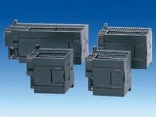
 .
.
Для просмотра информации в формате PDF необходимо установить Adobe Acrobat Reader.

- Несколько типов центральных процессоров.
- Различная производительность для максимальной адаптации к требованиям решаемой задачи.
 Дополнительную информацию Вы можете получить, нажав кнопку с этим символом.
Область применения
- CPU 221: компактный программируемый контроллер для решения простых задач автоматизации.
- CPU 222: компактный программируемый контроллер с возможностью подключения до 2 модулей расширения.
- CPU 224: компактный программируемый контроллер с возможностью подключения до 7 модулей расширения.
- CPU 224XP: компактный программируемый контроллер с возможностью подключения до 7 модулей расширения, двумя встроенными портами RS 485, встроенными дискретными и аналоговыми входами и выходами.
- CPU 226: программируемый контроллер с возможностью подключения до 7 модулей расширения и двумя встроенными портами RS 485.
Дизайн
- Горизонтальная или вертикальная установка на 35 мм профильную шину или на плоскую поверхность с креплением винтами через монтажные отверстия в корпусе.
- Съемные терминальные блоки с контактами под винт для подключения внешних цепей.
- Интерфейс для установки опционального модуля EEPROM-памяти.
- Интерфейс подключения модулей расширения (кроме CPU 221).
- 1 или 2 встроенных интерфейса RS 485.
- Переключатель выбора режимов работы.
- 1 или 2 потенциометра аналогового задания цифровых величин.
- Светодиодные индикаторы режимов работы и значений входных/ выходных дискретных сигналов.
- Защитные крышки токоведущих частей.
Технические данные (бумага)
| 6ES7 211-0AA23-0XB0 | 6ES7 211-0BA23-0XB0 | 6ES7 212-1AB23-0XB0 | 6ES7 212-1BB23-0XB0 | |
|---|---|---|---|---|
| Supply voltages | ||||
| Rated value | ||||
| - 24 V DC | Yes | Yes | ||
| - permissible range, lower limit (DC) | 20.4 V | 20.4 V | ||
| - permissible range, upper limit (DC) | 28.8 V | 28.8 V | ||
| - 120 V AC | Yes | Yes | ||
| - 230 V AC | Yes | Yes | ||
| - permissible range, lower limit (AC) | 85 V | 85 V | ||
| - permissible range, upper limit (AC) | 264 V | 264 V | ||
| - permissible frequency range, lower limit | 47 Hz | 47 Hz | ||
| - permissible frequency range, upper limit | 63 Hz | 63 Hz | ||
| Voltages and currents | ||||
| Load voltage L+ | ||||
| - Rated value (DC) | 24 V | 24 V | 24 V | 24 V |
| - permissible range, lower limit (DC) | 20.4 V | 5 V | 20.4 V | 5 V |
| - permissible range, upper limit (DC) | 28.8 V | 30 V | 28.8 V | 30 V |
| Load voltage L1 | ||||
| - Rated value (AC) | 100 V; 100 to 230 V AC | 100 V; 100 to 230 V AC | ||
| - permissible range, lower limit (AC) | 5 V | 5 V | ||
| - permissible range, upper limit (AC) | 250 V | 250 V | ||
| - permissible frequency range, lower limit | 47 Hz | 47 Hz | ||
| - permissible frequency range, upper limit | 63 Hz | 63 Hz | ||
| Current consumption | ||||
| - Inrush current, max. | 10 A; at 28.8 V | 20 A; at 264 V | 10 A; at 28.8 V | 20 A; at 264 V |
| - from supply voltage L+, max. | 450 mA; 80 to 450 mA | 500 mA; 85 to 500 mA, output current for expansion modules (5 V DC) 340 mA | ||
| - from supply voltage L1, max. | 120 mA; 15 to 60 mA (240 V), 30 to 120 mA (120 V); output current for expansion modules (5 V DC) 340 mA | 140 mA; 20 to 70 mA (240 V), 40 to 140 mA (120 V); output current for expansion modules (5 V DC) 340 mA | ||
| back-up battery | ||||
| - Backup time | 50 h; (min. 8 h at 40 °C); 200 days (typ.) with optional battery module | 50 h; (min. 8 h at 40 °C); 200 days (typ.) with optional battery module | 50 h; (min. 8 h at 40 °C); 200 days (typ.) with optional battery module | 50 h; (min. 8 h at 40 °C); 200 days (typ.) with optional battery module |
| Memory/backup | ||||
| Memory | ||||
| - Number of memory modules (optional) | 1; pluggable memory module, content identical to integral EEPROM, in addition, recipes, data logs and other files can be saved. | 1; pluggable memory module, content identical to integral EEPROM, in addition, recipes, data logs and other files can be saved. | 1; pluggable memory module, content identical to integral EEPROM, in addition, recipes, data logs and other files can be saved. | 1; pluggable memory module, content identical to integral EEPROM, in addition, recipes, data logs and other files can be saved. |
| - Data memory and program memory | ||||
| - Data memory, max. | 2 KByte | 2 KByte | 2 KByte | 2 KByte |
| - Program memory, max. | 4 KByte | 4 KByte | 4 KByte | 4 KByte |
| Backup | ||||
| - available | Yes; Program: entire program maintenance-free in integral EEPROM, programmable via CPU; data: entire DB 1 loaded from PG/PC maintenance-free in integral EEPROM, current values of DB 1 in RAM, retentive flags, timers, counters etc., maintenance free via super capacitor; optional battery | Yes; Program: entire program maintenance-free in integral EEPROM, programmable via CPU; data: entire DB 1 loaded from PG/PC maintenance-free in integral EEPROM, current values of DB 1 in RAM, retentive flags, timers, counters etc., maintenance free via super capacitor; optional battery | Yes; Program: entire program maintenance-free in integral EEPROM, programmable via CPU; data: entire DB 1 loaded from PG/PC maintenance-free in integral EEPROM, current values of DB 1 in RAM, retentive flags, timers, counters etc., maintenance free via super capacitor; optional battery | Yes; Program: entire program maintenance-free in integral EEPROM, programmable via CPU; data: entire DB 1 loaded from PG/PC maintenance-free in integral EEPROM, current values of DB 1 in RAM, retentive flags, timers, counters etc., maintenance free via super capacitor; optional battery |
| CPU/processing times | ||||
| - for bit instruction, max. | 0.22 µs | 0.22 µs | 0.22 µs | 0.22 µs |
| Timers/counters and their retentive characteristics | ||||
| S7 counter | ||||
| - Number | 256 | 256 | 256 | 256 |
| - of which retentive with battery | ||||
| - adjustable | Yes; via super capacitor or battery | Yes; via super capacitor or battery | Yes; via super capacitor or battery | Yes; via super capacitor or battery |
| - lower limit | 1 | 1 | 1 | 1 |
| - upper limit | 256 | 256 | 256 | 256 |
| - Counting range | ||||
| - lower limit | 0 | 0 | 0 | 0 |
| - upper limit | 32,767 | 32,767 | 32,767 | 32,767 |
| S7 times | ||||
| - Number | 256 | 256 | 256 | 256 |
| - of which retentive with battery | ||||
| - adjustable | Yes; via super capacitor or battery | Yes; via super capacitor or battery | Yes; via super capacitor or battery | Yes; via super capacitor or battery |
| - upper limit | 64 | 64 | 64 | 64 |
| - Timing range | ||||
| - lower limit | 1 ms | 1 ms | 1 ms | 1 ms |
| - upper limit | 54 min; 4 times, 1 ms to 30 s 16 times, 10 ms to 5 min 236 times, 100 ms to 54 min | 54 min; 4 times, 1 ms to 30 s 16 times, 10 ms to 5 min 236 times, 100 ms to 54 min | 54 min; 4 times, 1 ms to 30 s 16 times, 10 ms to 5 min 236 times, 100 ms to 54 min | 54 min; 4 times, 1 ms to 30 s 16 times, 10 ms to 5 min 236 times, 100 ms to 54 min |
| Data areas and their retentive characteristics | ||||
| Flags | ||||
| - Number | 32 Byte | 32 Byte | 32 Byte | 32 Byte |
| - adjustable retentivity | Yes; M0.0 to M31.7 | Yes; M0.0 to M31.7 | Yes; M0.0 to M31.7 | Yes; M0.0 to M31.7 |
| - of which retentive with battery | 0 to 255, via super capacitor or battery, adjustable | 0 to 255, via super capacitor or battery, adjustable | 0 to 255, via super capacitor or battery, adjustable | 0 to 255, via super capacitor or battery, adjustable |
| - of which retentive without battery | 0 to 112 in EEPROM, adjustable | 0 to 112 in EEPROM, adjustable | 0 to 112 in EEPROM, adjustable | 0 to 112 in EEPROM, adjustable |
| Configuration | ||||
| - Connectable programming devices/PCs | SIMATIC PG/PC, Standard PC | SIMATIC PG/PC, Standard PC | SIMATIC PG/PC, Standard PC | SIMATIC PG/PC, Standard PC |
| - Central units/expansion units, max. | 2 expansion modules. Only expansion modules of the S7-22x series can be used. Because of the limited output current, the use of expansion modules may be subject to restrictions. | 2 expansion modules. Only expansion modules of the S7-22x series can be used (because of the limited output current, the use of expansion modules may be subject to restrictions.) | ||
| I/O expansions | ||||
| - Analog inputs/outputs, max. | 10; max. 8 inputs and 2 outputs (EM) or max. 0 inputs and 4 outputs (EM) | 10; max. 8 inputs and 2 outputs (EM) or max. 0 inputs and 4 outputs (EM) | ||
| - Digital inputs/outputs, max. | 78; max. 40 inputs and 38 outputs (CPU+EM) | 78; max. 40 inputs and 38 outputs (CPU+EM) | ||
| - AS interface inputs/outputs, max. | 31; AS interface slaves (CP 243-2) | 31; AS interface slaves (CP 243-2) | ||
| Connection system | ||||
| - Pluggable I/O terminals | No | No | No | No |
| 1st interface | ||||
| - Type of interface | integrated RS 485 interface | integrated RS 485 interface | integrated RS 485 interface | integrated RS 485 interface |
| - Physical | RS 485 | RS 485 | RS 485 | RS 485 |
| Functionality | ||||
| - MPI | Yes; as MPI Slave for data exchange with MPI Masters (S7-300/S7-400-CPUs, OPs, TDs, Push Button Panels); internal S7-200 CPU/CPU communication is limited in the MPI network; transmission rates 19.2/187.5 kbit/s | Yes; as MPI Slave for data exchange with MPI Masters (S7-300/S7-400-CPUs, OPs, TDs, Push Button Panels); internal S7-200 CPU/CPU communication is limited in the MPI network; transmission rates 19.2/187.5 kbit/s | Yes; as MPI Slave for data exchange with MPI Masters (S7-300/S7-400-CPUs, OPs, TDs, Push Button Panels); internal S7-200 CPU/CPU communication is limited in the MPI network; transmission rates 19.2/187.5 kbit/s | Yes; as MPI Slave for data exchange with MPI Masters (S7-300/S7-400-CPUs, OPs, TDs, Push Button Panels); internal S7-200 CPU/CPU communication is limited in the MPI network; transmission rates 19.2/187.5 kbit/s |
| - PPI | Yes; with PPI protocol for programming functions, HMI functions (TD 200, OP), S7-200 internal CPU/CPU communication; transmission rates 9.6/19.2/187.5 kbit/s | Yes; with PPI protocol for programming functions, HMI functions (TD 200, OP), S7-200 internal CPU/CPU communication; transmission rates 9.6/19.2/187.5 kbit/s | Yes; with PPI protocol for programming functions, HMI functions (TD 200, OP), S7-200 internal CPU/CPU communication; transmission rates 9.6/19.2/187.5 kbit/s | Yes; with PPI protocol for programming functions, HMI functions (TD 200, OP), S7-200 internal CPU/CPU communication; transmission rates 9.6/19.2/187.5 kbit/s |
| - Serial data transmission | Yes; as a freely programmable interface with an interrupt option for serial data transmission with external units with ASCII ptotocol baud rates: 0.3/0.6/1.2/2.4/4.8/9.6/19.2/38.4 kbit/s; at 1.2 to 38.4 kbit/s, the PC/PPI cable can be used as an RS232/RS485 converter | Yes; as a freely programmable interface with an interrupt option for serial data transmission with external units with ASCII ptotocol baud rates: 0.3/0.6/1.2/2.4/4.8/9.6/19.2/38.4 kbit/s; at 1.2 to 38.4 kbit/s, the PC/PPI cable can be used as an RS232/RS485 converter | Yes; as a freely programmable interface with an interrupt option for serial data transmission with external units with ASCII ptotocol baud rates: 0.3/0.6/1.2/2.4/4.8/9.6/19.2/38.4 kbit/s; at 1.2 to 38.4 kbit/s, the PC/PPI cable can be used as an RS232/RS485 converter | Yes; as a freely programmable interface with an interrupt option for serial data transmission with external units with ASCII ptotocol baud rates: 0.3/0.6/1.2/2.4/4.8/9.6/19.2/38.4 kbit/s; at 1.2 to 38.4 kbit/s, the PC/PPI cable can be used as an RS232/RS485 converter |
| MPI | ||||
| - Transmission rates, max. | 187.5 kBit/s | 187.5 kBit/s | 187.5 kBit/s | 187.5 kBit/s |
| - Transmission rates, min. | 19.2 kBit/s | 19.2 kBit/s | 19.2 kBit/s | 19.2 kBit/s |
| CPU/ programming | ||||
| Programming language | ||||
| - KOP | Yes | Yes | Yes | Yes |
| - FUP | Yes | Yes | Yes | Yes |
| - AWL | Yes | Yes | Yes | Yes |
| - Instruction set | Bit logic instructions, compare instructions, timer instructions, counter instructions, clock instructions, integer math instructions, floating-point math instructions, numeric functions, move instructions, table instructions, logic instructions, shift and rotate instructions, conversion instructions, program control instructions, interrupt and communications instructions, logic stack instructions | Bit logic instructions, compare instructions, timer instructions, counter instructions, clock instructions, integer math instructions, floating-point math instructions, numeric functions, move instructions, table instructions, logic instructions, shift and rotate instructions, conversion instructions, program control instructions, interrupt and communications instructions, logic stack instructions | Bit logic instructions, compare instructions, timer instructions, counter instructions, clock instructions, integer math instructions, floating-point math instructions, numeric functions, move instructions, table instructions, logic instructions, shift and rotate instructions, conversion instructions, program control instructions, interrupt and communications instructions, logic stack instructions | Bit logic instructions, compare instructions, timer instructions, counter instructions, clock instructions, integer math instructions, floating-point math instructions, numeric functions, move instructions, table instructions, logic instructions, shift and rotate instructions, conversion instructions, program control instructions, interrupt and communications instructions, logic stack instructions |
| - User program protection/password protection | Yes; 3-stage password protection | Yes; 3-stage password protection | Yes; 3-stage password protection | Yes; 3-stage password protection |
| - Program execution | free cycle (OB 1), interrupt-driven, time-driven (1 to 255 ms) | free cycle (OB 1), interrupt-driven, time-driven (1 to 255 ms) | free cycle (OB 1), interrupt-driven, time-driven (1 to 255 ms) | free cycle (OB 1), interrupt-driven, time-driven (1 to 255 ms) |
| - Program organization | 1 OB, 1 DB, 1 SDB subprograms with/without parameter transfer | 1 OB, 1 DB, 1 SDB subprograms with/without parameter transfer | 1 OB, 1 DB, 1 SDB subprograms with/without parameter transfer | 1 OB, 1 DB, 1 SDB subprograms with/without parameter transfer |
| - Number of sub-programs, max. | 64 | 64 | 64 | 64 |
| Digital inputs | ||||
| - Number of digital inputs | 6; integrated | 6; integrated | 8 | 8 |
| Length of cable | ||||
| - Length of cable shielded, max | 500 m; Standard input: 500m, fast counters: 50m | 500 m; Standard input: 500m, fast counters: 50m | 500 m; Standard input: 500m, fast counters: 50m | 500 m; Standard input: 500m, fast counters: 50m |
| - Length of cable unshielded, max | 300 m; not for high-speed signals | 300 m; not for high-speed signals | 300 m; not for high-speed signals | 300 m; not for high-speed signals |
| - m/p reading | Yes; optional, per group | Yes; optional, per group | Yes; optional, per group | Yes; optional, per group |
| Input voltage | ||||
| - Rated value, DC | 24 V | 24 V | 24 V | 24 V |
| - for signal "0" | 0 to 5 V | 0 to 5 V | 0 to 5 V | 0 to 5 V |
| - for signal "1" | min. 15 V | min. 15 V | min. 15 V | min. 15 V |
| Input current | ||||
| - for 1 signal, typical | 2.5 mA | 2.5 mA | 2.5 mA | 2.5 mA |
| Input delay (at rated value of the input voltage) | ||||
| - For standard inputs | ||||
| - Parameterizable | Yes; all | Yes; all | Yes; all | Yes; all |
| - at 0 after 1, min. | 0.2 ms | 0.2 ms | 0.2 ms | 0.2 ms |
| - at 0 after 1, max. | 12.8 ms | 12.8 ms | 12.8 ms | 12.8 ms |
| - for alarm inputs | ||||
| - parameterizable | Yes; I0.0 to I0.3 | Yes; I0.0 to I0.3 | Yes; I0.0 to I0.3 | Yes; I0.0 to I0.3 |
| - for counters/technological functions | ||||
| - parameterizable | Yes; (E0.0 to E0.5) 30 kHz | Yes; (E0.0 to E0.5) 30 kHz | Yes; (E0.0 to E0.5) 30 kHz | Yes; (E0.0 to E0.5) 30 kHz |
| Digital outputs | ||||
| - Number of digital outputs | 4; Transistor | 4; Relay | 6; Transistor | 6; Relay |
| - Length of cable shielded, max. | 500 m | 500 m | 500 m | 500 m |
| - Length of cable unshielded, max. | 150 m | 150 m | 150 m | 150 m |
| - Short-circuit protection of the output | No; provided externally | No; provided externally | No; provided externally | No; provided externally |
| - Limitation of voltage induced on circuit interruption to | 1 W | 1 W | ||
| Switching capacity of the outputs | ||||
| - at resistive load, max. | 0.75 A | 2 A | 0.75 A | 2 A |
| - at lamp load, max. | 5 W | 30 W DC, 200 W AC | 5 W | 30 W DC, 200 W AC |
| Output voltage | ||||
| - for 1 signal | 20 V DC | L+/L1 | 20 V DC | L+/L1 |
| Output current | ||||
| - for 1 signal rated value | 750 mA | 2 A | 750 mA | 2 A |
| - for 0 signal residual current, max. | 0.1 mA | 0 mA | 10 μA | 0 mA |
| Output delay at resistive load | ||||
| - "0" after "1", max. | 15 µs; of standard outputs, max. (A0.2 to A0.3) 15 µs; of pulse outputs, max. (A0.0 to A0.1) 2 µs | 10 ms; all outputs | 15 µs; of standard outputs, max. (A0.2 to A0.5) 15 µs; of pulse outputs, max. (A0.0 to A0.1) 2 µs | 10 ms; all outputs |
| - "1" after "0", max. | 130 µs; of standard outputs, max. (A0.2 to A0.3) 100 µs; of pulse outputs, max. (A0.0 to A0.1) 10 µs | 10 ms; all outputs | 130 µs; of standard outputs, max. (A0.2 to A0.5) 100 µs; of pulse outputs, max. (A0.0 to A0.1) 10 µs | 10 ms; all outputs |
| Parallel switching of 2 outputs | ||||
| - to increase power | Yes | No | Yes | No |
| Switching frequency | ||||
| - of pulse outputs, at resistive load, max. | 20 kHz; A0.0 to A0.1 | 20 kHz; A0.0 to A0.1 | ||
| Summation current of the outputs (per group) | ||||
| - up to 40 °C, max. | 3 A | 6 A | 4.5 A | 6 A |
| - horizontal installation, up to 55 °C, max. | 3 A | 6 A | 4.5 A | 6 A |
| Relay outputs | ||||
| - Number of operating cycles | 10,000,000; mechanical 10 million, at rated load voltage 100,000 | 10,000,000; mechanical 10 million, at rated load voltage 100,000 | ||
| Analog inputs | ||||
| - Number of analog potentiometers | 1; Analog potentiometer; resolution 8 bits | 1; Analog potentiometer; resolution 8 bits | 1; Analog potentiometer; resolution 8 bits | 1; Analog potentiometer; resolution 8 bits |
| Sensor supply | ||||
| 24 V - sensor supply | ||||
| - 24 V | Yes; permissible range: 15.4 to 28.8 V | Yes; permissible range: 20.4 to 28.8 V | Yes; permissible range: 15.4 to 28.8 V | Yes; permissible range: 20.4 to 28.8 V |
| - Short-circuit protection | Yes; electronic at 600 mA | Yes; electronic at 600 mA | Yes; electronic at 600 mA | Yes; electronic at 600 mA |
| - Output current, max. | 180 mA | 180 mA | 180 mA | 180 mA |
| Sensor | ||||
| Connectable encoders | ||||
| - 2-wire BEROS | Yes | Yes | Yes | Yes |
| - permissible closed-circuit current (2-wire BEROS), max. | 1 mA | 1 mA | 1 mA | 1 mA |
| Integral functions | ||||
| - Number of counters | 4; fast counters (each 30 kHz), 32 bits (incl. sign), usable as up/down counter or for connecting 2 incremental encoders with 2 pulse trains offset by 90° (max. 20 kHz (A/B counter)); parameterizable enable and reset input; interrupt options (incl. Call up a sub-program with any content) when the setpoint value is reached; change of count direction etc. | 4; fast counters (each 30 kHz), 32 bits (incl. sign), usable as up/down counter or for connecting 2 incremental encoders with 2 pulse trains offset by 90° (max. 20 kHz (A/B counter)); parameterizable enable and reset input; interrupt options (incl. Call up a sub-program with any content) when the setpoint value is reached; change of count direction etc. | 4; fast counters (each 30 kHz), 32 bits (incl. sign), usable as up/down counter or for connecting 2 incremental encoders with 2 pulse trains offset by 90° (max. 20 kHz (A/B counter)); parameterizable enable and reset input; interrupt options (incl. Call up a sub-program with any content) when the setpoint value is reached; change of count direction etc. | 4; fast counters (each 30 kHz), 32 bits (incl. sign), usable as up/down counter or for connecting 2 incremental encoders with 2 pulse trains offset by 90° (max. 20 kHz (A/B counter)); parameterizable enable and reset input; interrupt options (incl. Call up a sub-program with any content) when the setpoint value is reached; change of count direction etc. |
| - Count frequency (counters) max. | 30 kHz | 30 kHz | 30 kHz | 30 kHz |
| - Number of alarm inputs | 4; 4 rising edges and/or 4 falling edges | 4; 4 rising edges and/or 4 falling edges | 4; 4 rising edges and/or 4 falling edges | 4; 4 rising edges and/or 4 falling edges |
| - Number of pulse outputs | 2; fast outputs, 20 kHz, with interrupt option; pulse width and frequency modulation | 2; fast outputs, 20 kHz, with interrupt option; pulse width and frequency modulation | 2; fast outputs, 20 kHz, with interrupt option; pulse width and frequency modulation | 2; fast outputs, 20 kHz, with interrupt option; pulse width and frequency modulation |
| - Cut-off frequency (pulse) | 20 kHz | 20 kHz | 20 kHz | 20 kHz |
| Potentials/ electrical isolation | ||||
| Digital output functions | ||||
| - between the channels | Yes; Optocoupler | Yes; Relay | Yes; Optocoupler | Yes; Relay |
| - between the channels, in groups of | 4 | 1 and 3 | 6 | 3 |
| Digital input functions | ||||
| - between the channels | Yes | Yes | Yes | Yes |
| - between the channels, in groups of | 2 and 4 | 2 and 4 | 4 | 4 |
| Permissible potential difference | ||||
| - between different circuits | 500 V DC between 24 V DC and 5 V DC | 500 V DC between 24 V DC and 5 V DC; 1500 V AC between 24 V DC and 230 V AC | 500 V DC between 24 V DC and 5 V DC | 500 V DC between 24 V DC and 5 V DC; 1500 V AC between 24 V DC and 230 V AC |
| Environmental requirements | ||||
| - Environmental conditions | For other ambient conditions: see "S7-200 Programmable Controller, System Manual" | For other ambient conditions: see "S7-200 Programmable Controller, System Manual" | For other ambient conditions: see "S7-200 Programmable Controller, System Manual" | For other ambient conditions: see "S7-200 Programmable Controller, System Manual" |
| Operating temperature | ||||
| - vertical mounting, min. | 0 °C | 0 °C | 0 °C | 0 °C |
| - vertical mounting, max. | 45 °C | 45 °C | 45 °C | 45 °C |
| - horizontal mounting, min. | 0 °C | 0 °C | 0 °C | 0 °C |
| - horizontal mounting, max. | 55 °C | 55 °C | 55 °C | 55 °C |
| Air pressure | ||||
| - permissible range, min | 860 hPa | 860 hPa | 860 hPa | 860 hPa |
| - permissible range, max | 1,080 hPa | 1,080 hPa | 1,080 hPa | 1,080 hPa |
| Relative humidity | ||||
| - Operation, min. | 5 % | 5 % | 5 % | 5 % |
| - Operation, max. | 95 %; RH stressing level 2 in accordance with IEC 1131-2 | 95 %; RH stressing level 2 in accordance with IEC 1131-2 | 95 %; RH stressing level 2 in accordance with IEC 1131-2 | 95 %; RH stressing level 2 in accordance with IEC 1131-2 |
| Degree of protection and class of protection | ||||
| - IP 20 | Yes | Yes | Yes | Yes |
| Dimensions and weight | ||||
| - Weight, approx. | 270 g | 310 g | 270 g | 310 g |
| - Width | 90 mm | 90 mm | 90 mm | 90 mm |
| - Height | 80 mm | 80 mm | 80 mm | 80 mm |
| - Depth | 62 mm | 62 mm | 62 mm | 62 mm |
| 6ES7 214-1AD23-0XB0 | 6ES7 214-1BD23-0XB0 | 6ES7 214-2AD23-0XB0 | 6ES7 214-2BD23-0XB0 | 6ES7 216-2AD23-0XB0 | 6ES7 216-2BD23-0XB0 | |
|---|---|---|---|---|---|---|
| Supply voltages | ||||||
| Rated value | ||||||
| - 24 V DC | Yes | Yes | Yes | |||
| - permissible range, lower limit (DC) | 20.4 V | 20.4 V | 20.4 V | |||
| - permissible range, upper limit (DC) | 28.8 V | 28.8 V | 28.8 V | |||
| - 120 V AC | Yes | Yes | Yes | |||
| - 230 V AC | Yes | Yes | Yes | |||
| - permissible range, lower limit (AC) | 85 V | 85 V | 85 V | |||
| - permissible range, upper limit (AC) | 264 V | 264 V | 264 V | |||
| - permissible frequency range, lower limit | 47 Hz | 47 Hz | 47 Hz | |||
| - permissible frequency range, upper limit | 63 Hz | 63 Hz | 63 Hz | |||
| Voltages and currents | ||||||
| Load voltage L+ | ||||||
| - Rated value (DC) | 24 V | 24 V | 24 V | 24 V | 24 V | 24 V |
| - permissible range, lower limit (DC) | 20.4 V | 5 V | 20.4 V | 5 V | 20.4 V | 5 V |
| - permissible range, upper limit (DC) | 28.8 V | 30 V | 28.8 V | 30 V | 28.8 V | 30 V |
| Load voltage L1 | ||||||
| - Rated value (AC) | 100 V; 100 to 230 V AC | 100 V; 100 to 230 V AC | 100 V; 100 to 230 V AC | |||
| - permissible range, lower limit (AC) | 5 V | 5 V | 5 V | |||
| - permissible range, upper limit (AC) | 250 V | 250 V | 250 V | |||
| - permissible frequency range, lower limit | 47 Hz | 47 Hz | 47 Hz | |||
| - permissible frequency range, upper limit | 63 Hz | 63 Hz | 63 Hz | |||
| Current consumption | ||||||
| - Inrush current, max. | 12 A; at 28.8 V | 20 A; at 264 V | 12 A; at 28.8 V | 20 A; at 264 V | 10 A; at 28.8 V | 20 A; at 264 V |
| - from supply voltage L+, max. | 700 mA; 110 to 700 mA, output current for expansion modules (5 V DC) 660 mA | 900 mA; 120 to 900 mA, output current for expansion modules (5 V DC) 660 mA | 1,050 mA; 150 to 1050 mA, output current for expansion modules (5 V DC) 1000 mA | |||
| - from supply voltage L1, max. | 200 mA; 30 to 100 mA (240 V), 60 to 200 mA (120 V); output current for expansion modules (5 V DC) 600 mA | 220 mA; 35 to 100 mA (240 V), 70 to 220 mA (120 V); output current for expansion modules (5 V DC) 600 mA | 320 mA; 40 to 160 mA (240 V), 80 to 320 mA (120 V); output current for expansion modules (5 V DC) 1000 mA | |||
| back-up battery | ||||||
| - Backup time | 100 h; (min. 70 h at 40 °C); 200 days (typ.) with optional battery module | 100 h; (min. 70 h at 40 °C); 200 days (typ.) with optional battery module | 100 h; (min. 70 h at 40 °C); 200 days (typ.) with optional battery module | 100 h; (min. 70 h at 40 °C); 200 days (typ.) with optional battery module | 100 h; (min. 70 h at 40 °C); 200 days (typ.) with optional battery module | 100 h; (min. 70 h at 40 °C); 200 days (typ.) with optional battery module |
| Memory/backup | ||||||
| Memory | ||||||
| - Number of memory modules (optional) | 1; pluggable memory module, content identical to integral EEPROM, in addition, recipes, data logs and other files can be saved. | 1; pluggable memory module, content identical to integral EEPROM, in addition, recipes, data logs and other files can be saved. | 1; pluggable memory module, content identical to integral EEPROM, in addition, recipes, data logs and other files can be saved. | 1; pluggable memory module, content identical to integral EEPROM, in addition, recipes, data logs and other files can be saved. | 1; pluggable memory module, content identical to integral EEPROM, in addition, recipes, data logs and other files can be saved. | 1; pluggable memory module, content identical to integral EEPROM, in addition, recipes, data logs and other files can be saved. |
| - Data memory and program memory | ||||||
| - Data memory, max. | 8 KByte | 8 KByte | 10 KByte | 10 KByte | 10 KByte | 10 KByte |
| - Program memory, max. | 12 KByte; 8 Kbytes for active run-time edit | 12 KByte; 8 Kbytes for active run-time edit | 16 KByte; 12 Kbytes for active run-time edit | 16 KByte; 12 Kbytes for active run-time edit | 24 KByte; 16 Kbytes with active run-time edit | 24 KByte; 16 Kbytes with active run-time edit |
| Backup | ||||||
| - available | Yes; Program: entire program maintenance-free in integral EEPROM, programmable via CPU; data: entire DB 1 loaded from PG/PC maintenance-free in integral EEPROM, current values of DB 1 in RAM, retentive flags, timers, counters etc., maintenance free via super capacitor; optional battery | Yes; Program: entire program maintenance-free in integral EEPROM, programmable via CPU; data: entire DB 1 loaded from PG/PC maintenance-free in integral EEPROM, current values of DB 1 in RAM, retentive flags, timers, counters etc., maintenance free via super capacitor; optional battery | Yes; Program: entire program maintenance-free in integral EEPROM, programmable via CPU; data: entire DB 1 loaded from PG/PC maintenance-free in integral EEPROM, current values of DB 1 in RAM, retentive flags, timers, counters etc., maintenance free via super capacitor; optional battery | Yes; Program: entire program maintenance-free in integral EEPROM, programmable via CPU; data: entire DB 1 loaded from PG/PC maintenance-free in integral EEPROM, current values of DB 1 in RAM, retentive flags, timers, counters etc., maintenance free via super capacitor; optional battery | Yes; Program: entire program maintenance-free in integral EEPROM, programmable via CPU; data: entire DB 1 loaded from PG/PC maintenance-free in integral EEPROM, current values of DB 1 in RAM, retentive flags, timers, counters etc., maintenance free via super capacitor; optional battery | Yes; Program: entire program maintenance-free in integral EEPROM, programmable via CPU; data: entire DB 1 loaded from PG/PC maintenance-free in integral EEPROM, current values of DB 1 in RAM, retentive flags, timers, counters etc., maintenance free via super capacitor; optional battery |
| CPU/processing times | ||||||
| - for bit instruction, max. | 0.22 µs | 0.22 µs | 0.22 µs | 0.22 µs | 0.22 µs | 0.22 µs |
| Timers/counters and their retentive characteristics | ||||||
| S7 counter | ||||||
| - Number | 256 | 256 | 256 | 256 | 256 | 256 |
| - of which retentive with battery | ||||||
| - adjustable | Yes; via super capacitor or battery | Yes; via super capacitor or battery | Yes; via super capacitor or battery | Yes; via super capacitor or battery | Yes; via super capacitor or battery | Yes; via super capacitor or battery |
| - lower limit | 1 | 1 | 1 | 1 | 1 | 1 |
| - upper limit | 256 | 256 | 256 | 256 | 256 | 256 |
| - Counting range | ||||||
| - lower limit | 0 | 0 | 0 | 0 | 0 | 0 |
| - upper limit | 32,767 | 32,767 | 32,767 | 32,767 | 32,767 | 32,767 |
| S7 times | ||||||
| - Number | 256 | 256 | 256 | 256 | 256 | 256 |
| - of which retentive with battery | ||||||
| - adjustable | Yes; via super capacitor or battery | Yes; via super capacitor or battery | Yes; via super capacitor or battery | Yes; via super capacitor or battery | Yes; via super capacitor or battery | Yes; via super capacitor or battery |
| - upper limit | 64 | 64 | 64 | 64 | 64 | 64 |
| - Timing range | ||||||
| - lower limit | 1 ms | 1 ms | 1 ms | 1 ms | 1 ms | 1 ms |
| - upper limit | 54 min; 4 times, 1 ms to 30 s 16 times, 10 ms to 5 min 236 times, 100 ms to 54 min | 54 min; 4 times, 1 ms to 30 s 16 times, 10 ms to 5 min 236 times, 100 ms to 54 min | 54 min; 4 times, 1 ms to 30 s 16 times, 10 ms to 5 min 236 times, 100 ms to 54 min | 54 min; 4 times, 1 ms to 30 s 16 times, 10 ms to 5 min 236 times, 100 ms to 54 min | 54 min; 4 times, 1 ms to 30 s 16 times, 10 ms to 5 min 236 times, 100 ms to 54 min | 54 min; 4 times, 1 ms to 30 s 16 times, 10 ms to 5 min 236 times, 100 ms to 54 min |
| Data areas and their retentive characteristics | ||||||
| Flags | ||||||
| - Number | 32 Byte | 32 Byte | 32 Byte | 32 Byte | 32 Byte | 32 Byte |
| - adjustable retentivity | Yes; M0.0 to M31.7 | Yes; M0.0 to M31.7 | Yes; M0.0 to M31.7 | Yes; M0.0 to M31.7 | Yes; M0.0 to M31.7 | Yes; M0.0 to M31.7 |
| - of which retentive with battery | 0 to 255, via super capacitor or battery, adjustable | 0 to 255, via super capacitor or battery, adjustable | 0 to 255, via super capacitor or battery, adjustable | 0 to 255, via super capacitor or battery, adjustable | 0 to 255, via super capacitor or battery, adjustable | 0 to 255, via super capacitor or battery, adjustable |
| - of which retentive without battery | 0 to 112 in EEPROM, adjustable | 0 to 112 in EEPROM, adjustable | 0 to 112 in EEPROM, adjustable | 0 to 112 in EEPROM, adjustable | 0 to 112 in EEPROM, adjustable | 0 to 112 in EEPROM, adjustable |
| Configuration | ||||||
| - Connectable programming devices/PCs | SIMATIC PG/PC, Standard PC | SIMATIC PG/PC, Standard PC | SIMATIC PG/PC, Standard PC | SIMATIC PG/PC, Standard PC | SIMATIC PG/PC, Standard PC | SIMATIC PG/PC, Standard PC |
| - Central units/expansion units, max. | 7 expansion modules. Only expansion modules of the S7-22x series can be used. (Because of the limited output current, the use of expansion modules may be subject to restrictions.) | 7 expansion modules. Only expansion modules of the S7-22x series can be used. (Because of the limited output current, the use of expansion modules may be subject to restrictions.) | 7 expansion modules. Only expansion modules of the S7-22x series can be used. (Because of the limited output current, the use of expansion modules may be subject to restrictions.) | 7 expansion modules. Only expansion modules of the S7-22x series can be used. (Because of the limited output current, the use of expansion modules may be subject to restrictions.) | 7 expansion modules. Only expansion modules of the S7-22x series can be used. (Because of the limited output current, the use of expansion modules may be subject to restrictions.) | 7 expansion modules. Only expansion modules of the S7-22x series can be used. (Because of the limited output current, the use of expansion modules may be subject to restrictions.) |
| I/O expansions | ||||||
| - Analog inputs/outputs, max. | 35; max. 28 inputs and 7 outputs (EM) or max. 0 inputs and 14 outputs (EM) | 35; max. 28 inputs and 7 outputs (EM) or max. 0 inputs and 14 outputs (EM) | 38; 2 on board inputs and one output, in addition max. 28 inputs and 7 outputs (EM) or max. 0 inputs and 14 outputs (EM) | 38; 2 on board inputs and one output, in addition max. 28 inputs and 7 outputs (EM) or max. 0 inputs and 14 outputs (EM) | 35; max. 28 inputs and 7 outputs (EM) or max. 0 inputs and 14 outputs (EM) | 35; max. 28 inputs and 7 outputs (EM) or max. 0 inputs and 14 outputs (EM) |
| - Digital inputs/outputs, max. | 168; max. 94 inputs and 74 outputs (CPU+EM) | 168; max. 94 inputs and 74 outputs (CPU+EM) | 168; max. 94 inputs and 74 outputs (CPU+EM) | 168; max. 94 inputs and 74 outputs (CPU+EM) | 148; max. 128 inputs and 120 outputs (CPU+EM) | 148; max. 128 inputs and 120 outputs (CPU+EM) |
| - AS interface inputs/outputs, max. | 62; AS interface A/B slaves (CP 243-2) | 62; AS interface A/B slaves (CP 243-2) | 62; AS interface A/B slaves (CP 243-2) | 62; AS interface A/B slaves (CP 243-2) | 62; AS interface A/B slaves (CP 243-2) | 62; AS interface A/B slaves (CP 243-2) |
| Connection system | ||||||
| - Pluggable I/O terminals | Yes | Yes | Yes | Yes | Yes | Yes |
| 1st interface | ||||||
| - Type of interface | integrated RS 485 interface | integrated RS 485 interface | integrated RS 485 interface | integrated RS 485 interface | integrated RS 485 interface | integrated RS 485 interface |
| - Physical | RS 485 | RS 485 | RS 485 | RS 485 | RS 485 | RS 485 |
| Functionality | ||||||
| - MPI | Yes; as MPI Slave for data exchange with MPI Masters (S7-300/S7-400-CPUs, OPs, TDs, Push Button Panels); internal S7-200 CPU/CPU communication is limited in the MPI network; transmission rates 19.2/187.5 kbit/s | Yes; as MPI Slave for data exchange with MPI Masters (S7-300/S7-400-CPUs, OPs, TDs, Push Button Panels); internal S7-200 CPU/CPU communication is limited in the MPI network; transmission rates 19.2/187.5 kbit/s | Yes; as MPI Slave for data exchange with MPI Masters (S7-300/S7-400-CPUs, OPs, TDs, Push Button Panels); internal S7-200 CPU/CPU communication is limited in the MPI network; transmission rates 19.2/187.5 kbit/s | Yes; as MPI Slave for data exchange with MPI Masters (S7-300/S7-400-CPUs, OPs, TDs, Push Button Panels); internal S7-200 CPU/CPU communication is limited in the MPI network; transmission rates 19.2/187.5 kbit/s | Yes; as MPI Slave for data exchange with MPI Masters (S7-300/S7-400-CPUs, OPs, TDs, Push Button Panels); internal S7-200 CPU/CPU communication is limited in the MPI network; transmission rates 19.2/187.5 kbit/s | Yes; as MPI Slave for data exchange with MPI Masters (S7-300/S7-400-CPUs, OPs, TDs, Push Button Panels); internal S7-200 CPU/CPU communication is limited in the MPI network; transmission rates 19.2/187.5 kbit/s |
| - PPI | Yes; with PPI protocol for programming functions, HMI functions (TD 200, OP), S7-200 internal CPU/CPU communication; transmission rates 9.6/19.2/187.5 kbit/s | Yes; with PPI protocol for programming functions, HMI functions (TD 200, OP), S7-200 internal CPU/CPU communication; transmission rates 9.6/19.2/187.5 kbit/s | Yes; with PPI protocol for programming functions, HMI functions (TD 200, OP), S7-200 internal CPU/CPU communication; transmission rates 9.6/19.2/187.5 kbit/s | Yes; with PPI protocol for programming functions, HMI functions (TD 200, OP), S7-200 internal CPU/CPU communication; transmission rates 9.6/19.2/187.5 kbit/s | Yes; with PPI protocol for programming functions, HMI functions (TD 200, OP), S7-200 internal CPU/CPU communication; transmission rates 9.6/19.2/187.5 kbit/s | Yes; with PPI protocol for programming functions, HMI functions (TD 200, OP), S7-200 internal CPU/CPU communication; transmission rates 9.6/19.2/187.5 kbit/s |
| - Serial data transmission | Yes; as a freely programmable interface with an interrupt option for serial data transmission with external units with ASCII ptotocol baud rates: 0.3/0.6/1.2/2.4/4.8/9.6/19.2/38.4 kbit/s; at 1.2 to 38.4 kbit/s, the PC/PPI cable can be used as an RS232/RS485 converter | Yes; as a freely programmable interface with an interrupt option for serial data transmission with external units with ASCII ptotocol baud rates: 0.3/0.6/1.2/2.4/4.8/9.6/19.2/38.4 kbit/s; at 1.2 to 38.4 kbit/s, the PC/PPI cable can be used as an RS232/RS485 converter | Yes; as a freely programmable interface with an interrupt option for serial data transmission with external units with ASCII ptotocol baud rates: 0.3/0.6/1.2/2.4/4.8/9.6/19.2/38.4 kbit/s; at 1.2 to 38.4 kbit/s, the PC/PPI cable can be used as an RS232/RS485 converter | Yes; as a freely programmable interface with an interrupt option for serial data transmission with external units with ASCII ptotocol baud rates: 0.3/0.6/1.2/2.4/4.8/9.6/19.2/38.4 kbit/s; at 1.2 to 38.4 kbit/s, the PC/PPI cable can be used as an RS232/RS485 converter | Yes; as a freely programmable interface with an interrupt option for serial data transmission with external units with ASCII ptotocol baud rates: 0.3/0.6/1.2/2.4/4.8/9.6/19.2/38.4 kbit/s; at 1.2 to 38.4 kbit/s, the PC/PPI cable can be used as an RS232/RS485 converter | Yes; as a freely programmable interface with an interrupt option for serial data transmission with external units with ASCII ptotocol baud rates: 0.3/0.6/1.2/2.4/4.8/9.6/19.2/38.4 kbit/s; at 1.2 to 38.4 kbit/s, the PC/PPI cable can be used as an RS232/RS485 converter |
| MPI | ||||||
| - Transmission rates, max. | 187.5 kBit/s | 187.5 kBit/s | 187.5 kBit/s | 187.5 kBit/s | 187.5 kBit/s | 187.5 kBit/s |
| - Transmission rates, min. | 19.2 kBit/s | 19.2 kBit/s | 19.2 kBit/s | 19.2 kBit/s | 19.2 kBit/s | 19.2 kBit/s |
| 2nd interface | ||||||
| - Type of interface | integrated RS 485 interface | integrated RS 485 interface | integrated RS 485 interface | integrated RS 485 interface | ||
| - Physical | RS 485 | RS 485 | RS 485 | RS 485 | ||
| Functionality | ||||||
| - MPI | Yes; as MPI Slave for data exchange with MPI Masters (S7-300/S7-400-CPUs, OPs, TDs, Push Button Panels); internal S7-200 CPU/CPU communication is limited in the MPI network; transmission rates 19.2/187.5 kbit/s | Yes; as MPI Slave for data exchange with MPI Masters (S7-300/S7-400-CPUs, OPs, TDs, Push Button Panels); internal S7-200 CPU/CPU communication is limited in the MPI network; transmission rates 19.2/187.5 kbit/s | Yes; as MPI Slave for data exchange with MPI Masters (S7-300/S7-400-CPUs, OPs, TDs, Push Button Panels); internal S7-200 CPU/CPU communication is limited in the MPI network; transmission rates 19.2/187.5 kbit/s | Yes; as MPI Slave for data exchange with MPI Masters (S7-300/S7-400-CPUs, OPs, TDs, Push Button Panels); internal S7-200 CPU/CPU communication is limited in the MPI network; transmission rates 19.2/187.5 kbit/s | ||
| - Functionality PPI | Yes; with PPI protocol for programming functions, HMI functions (TD 200, OP), S7-200 internal CPU/CPU communication; transmission rates 9.6/19.2/187.5 kbit/s | Yes; with PPI protocol for programming functions, HMI functions (TD 200, OP), S7-200 internal CPU/CPU communication; transmission rates 9.6/19.2/187.5 kbit/s | Yes; with PPI protocol for programming functions, HMI functions (TD 200, OP), S7-200 internal CPU/CPU communication; transmission rates 9.6/19.2/187.5 kbit/s | Yes; with PPI protocol for programming functions, HMI functions (TD 200, OP), S7-200 internal CPU/CPU communication; transmission rates 9.6/19.2/187.5 kbit/s | ||
| - Serial data transmission | Yes; as a freely programmable interface with an interrupt option for serial data transmission with external units with ASCII ptotocol baud rates: 0.3/0.6/1.2/2.4/4.8/9.6/19.2/38.4 kbit/s; at 1.2 to 38.4 kbit/s, the PC/PPI cable can be used as an RS232/RS485 converter | Yes; as a freely programmable interface with an interrupt option for serial data transmission with external units with ASCII ptotocol baud rates: 0.3/0.6/1.2/2.4/4.8/9.6/19.2/38.4 kbit/s; at 1.2 to 38.4 kbit/s, the PC/PPI cable can be used as an RS232/RS485 converter | Yes; as a freely programmable interface with an interrupt option for serial data transmission with external units with ASCII ptotocol baud rates: 0.3/0.6/1.2/2.4/4.8/9.6/19.2/38.4 kbit/s; at 1.2 to 38.4 kbit/s, the PC/PPI cable can be used as an RS232/RS485 converter | Yes; as a freely programmable interface with an interrupt option for serial data transmission with external units with ASCII ptotocol baud rates: 0.3/0.6/1.2/2.4/4.8/9.6/19.2/38.4 kbit/s; at 1.2 to 38.4 kbit/s, the PC/PPI cable can be used as an RS232/RS485 converter | ||
| MPI | ||||||
| - Transmission rate, max. | 187.5 kBit/s | 187.5 kBit/s | 187.5 kBit/s | 187.5 kBit/s | ||
| - Transmission rate, min. | 19.2 kBit/s | 19.2 kBit/s | 19.2 kBit/s | 19.2 kBit/s | ||
| CPU/ programming | ||||||
| Programming language | ||||||
| - KOP | Yes | Yes | Yes | Yes | Yes | Yes |
| - FUP | Yes | Yes | Yes | Yes | Yes | Yes |
| - AWL | Yes | Yes | Yes | Yes | Yes | Yes |
| - Instruction set | Bit logic instructions, compare instructions, timer instructions, counter instructions, clock instructions, integer math instructions, floating-point math instructions, numeric functions, move instructions, table instructions, logic instructions, shift and rotate instructions, conversion instructions, program control instructions, interrupt and communications instructions, logic stack instructions | Bit logic instructions, compare instructions, timer instructions, counter instructions, clock instructions, integer math instructions, floating-point math instructions, numeric functions, move instructions, table instructions, logic instructions, shift and rotate instructions, conversion instructions, program control instructions, interrupt and communications instructions, logic stack instructions | Bit logic instructions, compare instructions, timer instructions, counter instructions, clock instructions, integer math instructions, floating-point math instructions, numeric functions, move instructions, table instructions, logic instructions, shift and rotate instructions, conversion instructions, program control instructions, interrupt and communications instructions, logic stack instructions | Bit logic instructions, compare instructions, timer instructions, counter instructions, clock instructions, integer math instructions, floating-point math instructions, numeric functions, move instructions, table instructions, logic instructions, shift and rotate instructions, conversion instructions, program control instructions, interrupt and communications instructions, logic stack instructions | Bit logic instructions, compare instructions, timer instructions, counter instructions, clock instructions, integer math instructions, floating-point math instructions, numeric functions, move instructions, table instructions, logic instructions, shift and rotate instructions, conversion instructions, program control instructions, interrupt and communications instructions, logic stack instructions | Bit logic instructions, compare instructions, timer instructions, counter instructions, clock instructions, integer math instructions, floating-point math instructions, numeric functions, move instructions, table instructions, logic instructions, shift and rotate instructions, conversion instructions, program control instructions, interrupt and communications instructions, logic stack instructions |
| - User program protection/password protection | Yes; 3-stage password protection | Yes; 3-stage password protection | Yes; 3-stage password protection | Yes; 3-stage password protection | Yes; 3-stage password protection | Yes; 3-stage password protection |
| - Program execution | free cycle (OB 1), interrupt-driven, time-driven (1 to 255 ms) | free cycle (OB 1), interrupt-driven, time-driven (1 to 255 ms) | free cycle (OB 1), interrupt-driven, time-driven (1 to 255 ms) | free cycle (OB 1), interrupt-driven, time-driven (1 to 255 ms) | free cycle (OB 1), interrupt-driven, time-driven (1 to 255 ms) | free cycle (OB 1), interrupt-driven, time-driven (1 to 255 ms) |
| - Program organization | 1 OB, 1 DB, 1 SDB subprograms with/without parameter transfer | 1 OB, 1 DB, 1 SDB subprograms with/without parameter transfer | 1 OB, 1 DB, 1 SDB subprograms with/without parameter transfer | 1 OB, 1 DB, 1 SDB subprograms with/without parameter transfer | 1 OB, 1 DB, 1 SDB subprograms with/without parameter transfer | 1 OB, 1 DB, 1 SDB subprograms with/without parameter transfer |
| - Number of sub-programs, max. | 64 | 64 | 64 | 64 | 64 | 64 |
| Digital inputs | ||||||
| - Number of digital inputs | 14 | 14 | 14 | 14 | 24 | 24 |
| Length of cable | ||||||
| - Length of cable shielded, max | 500 m; Standard input: 500m, fast counters: 50m | 500 m; Standard input: 500m, fast counters: 50m | 500 m; Standard input: 500m, fast counters: 50m | 500 m; Standard input: 500m, fast counters: 50m | 500 m; Standard input: 500m, fast counters: 50m | 500 m; Standard input: 500m, fast counters: 50m |
| - Length of cable unshielded, max | 300 m; not for high-speed signals | 300 m; not for high-speed signals | 300 m; not for high-speed signals | 300 m; not for high-speed signals | 300 m; not for high-speed signals | 300 m; not for high-speed signals |
| - m/p reading | Yes; optional, per group | Yes; optional, per group | Yes; optional, per group | Yes; optional, per group | Yes; optional, per group | Yes; optional, per group |
| Input voltage | ||||||
| - Rated value, DC | 24 V | 24 V | 24 V | 24 V | 24 V | 24 V |
| - for signal "0" | 0 to 5 V | 0 to 5 V | 0 to 5 V; 0 to 1V (I0.3 to I0.5) | 0 to 5 V 0 to 1V (I0.3 to I0.5) | 0 to 5 V | 0 to 5 V |
| - for signal "1" | min. 15 V | min. 15 V | min. 15 V; at least 4V (I0.3 to I0.5) | min. 15 V at least 4V (I0.3 to I0.5) | min. 15 V | min. 15 V |
| Input current | ||||||
| - for 1 signal, typical | 2.5 mA | 2.5 mA | 2.5 mA; 8 mA for I0.3 to I0.5 | 2.5 mA; 8 mA for I0.3 to I0.5 | 2.5 mA | 2.5 mA |
| Input delay (at rated value of the input voltage) | ||||||
| - For standard inputs | ||||||
| - Parameterizable | Yes; all | Yes; all | Yes; all | Yes; all | Yes; all | Yes; all |
| - at 0 after 1, min. | 0.2 ms | 0.2 ms | 0.2 ms | 0.2 ms | 0.2 ms | 0.2 ms |
| - at 0 after 1, max. | 12.8 ms | 12.8 ms | 12.8 ms | 12.8 ms | 12.8 ms | 12.8 ms |
| - for alarm inputs | ||||||
| - parameterizable | Yes; I0.0 to I0.3 | Yes; I0.0 to I0.3 | Yes; I0.0 to I0.3 | Yes; I0.0 to I0.3 | Yes; I0.0 to I0.3 | Yes; I0.0 to I0.3 |
| - for counters/technological functions | ||||||
| - parameterizable | Yes; (E0.0 to E1.5) 30 kHz | Yes; (E0.0 to E1.5) 30 kHz | Yes; (E0.0 to E1.5) up to 200 kHz | Yes; (E0.0 to E1.5) up to 200 kHz | Yes; (E0.0 to E1.5) 30 kHz | Yes; (E0.0 to E1.5) 30 kHz |
| Digital outputs | ||||||
| - Number of digital outputs | 10; Transistor | 10; Relay | 10; Transistor | 10; Relay | 16; Transistor | 16; Relay |
| - Length of cable shielded, max. | 500 m | 500 m | 500 m | 500 m | 500 m | 500 m |
| - Length of cable unshielded, max. | 150 m | 150 m | 150 m | 150 m | 150 m | 150 m |
| - Short-circuit protection of the output | No; provided externally | No; provided externally | No; provided externally | No; provided externally | No; provided externally | No; provided externally |
| - Limitation of voltage induced on circuit interruption to | 1 W | 1 W | 1 W | |||
| Switching capacity of the outputs | ||||||
| - at resistive load, max. | 0.75 A | 2 A | 0.75 A | 2 A | 0.75 A | 2 A |
| - at lamp load, max. | 5 W | 200 W; 30 W DC, 200 W AC | 5 W | 200 W; 30 W DC, 200 W AC | 5 W | 200 W; 30 W DC, 200 W AC |
| Output voltage | ||||||
| - for 1 signal | 20 V DC | L+/L1 | L+ minus 0.4V (5V/20,4V for A0.0 to A0.4; 20,4V A0.5 to A1.1) | L+/L1 | 20 V DC | L+/L1 |
| Output current | ||||||
| - for 1 signal rated value | 750 mA | 2 A | 750 mA | 2 A | 750 mA | 2 A |
| - for 0 signal residual current, max. | 10 μA | 0 mA | 10 μA | 0 mA | 10 μA | 0 mA |
| Output delay at resistive load | ||||||
| - "0" after "1", max. | 15 µs; of the standard outputs, max. (A0.2 to A1.1) 2 µs; of the pulse outputs, max. (A0.0 to A0.1) 2 µs | 10 ms; all outputs | 15 µs; of the standard outputs, max. (A0.2 to A1.1) 15 µs; of the pulse outputs, max. (A0.0 to A0.1) 0.5 µs | 10 ms; all outputs | 15 µs; of the standard outputs, max. (A0.2 to A1.1) 2 µs; of the pulse outputs, max. (A0.0 to A0.1) 2 µs | 10 ms; all outputs |
| - "1" after "0", max. | 130 µs; of the standard outputs, max. (A0.2 to A1.1) 10 µs; of the pulse outputs, max. (A0.0 to A0.1) 10 µs | 10 ms; all outputs | 130 µs; of the standard outputs, max. (A0.2 to A1.1) 130 µs; of the pulse outputs, max. (A0.0 to A0.1) 1.5 µs | 10 ms; all outputs | 130 µs; of the standard outputs, max. (A0.2 to A1.1) 10 µs; of the pulse outputs, max. (A0.0 to A0.1) 10 µs | 10 ms; all outputs |
| Parallel switching of 2 outputs | ||||||
| - to increase power | Yes | No | Yes | No | Yes | No |
| Switching frequency | ||||||
| - of pulse outputs, at resistive load, max. | 20 kHz; A0.0 to A0.1 | 1 Hz | 100 kHz; A0.0 to A0.1 | 1 Hz | 20 kHz; A0.0 to A0.1 | 1 kHz |
| Summation current of the outputs (per group) | ||||||
| - up to 40 °C, max. | 6 A | 10 A | 3.75 A | 10 A | 6 A | 10 A |
| - horizontal installation, up to 55 °C, max. | 6 A | 10 A | 3.75 A | 10 A | 6 A | 10 A |
| Relay outputs | ||||||
| - Number of operating cycles | 10,000,000; mechanical 10 million, at rated load voltage 100,000 | 10,000,000; mechanical 10 million, at rated load voltage 100,000 | 10,000,000; mechanical 10 million, at rated load voltage 100,000 | |||
| Analog inputs | ||||||
| - Number of analog potentiometers | 2; Analog potentiometer; resolution 8 bits | 2; Analog potentiometer; resolution 8 bits | 2; Analog potentiometer; resolution 8 bits | 2; Analog potentiometer; resolution 8 bits | 2; Analog potentiometer; resolution 8 bits | 2; Analog potentiometer; resolution 8 bits |
| Sensor supply | ||||||
| 24 V - sensor supply | ||||||
| - 24 V | Yes; permissible range: 15.4 to 28.8 V | Yes; permissible range: 20.4 to 28.8 V | Yes; permissible range: 15.4 to 28.8 V | Yes; permissible range: 20.4 to 28.8 V | Yes; permissible range: 15.4 to 28.8 V | Yes; permissible range: 20.4 to 28.8 V |
| - Short-circuit protection | Yes; electronic at 280 mA | Yes; electronic at 280 mA | Yes; electronic at 280 mA | Yes; electronic at 280 mA | Yes; electronic at 400 mA | Yes; electronic at 400mA |
| - Output current, max. | 280 mA | 280 mA | 280 mA | 280 mA | 400 mA | 400 mA |
| Sensor | ||||||
| Connectable encoders | ||||||
| - 2-wire BEROS | Yes | Yes | Yes | Yes | Yes | Yes |
| - permissible closed-circuit current (2-wire BEROS), max. | 1 mA | 1 mA | 1 mA | 1 mA | 1 mA | 1 mA |
| Integral functions | ||||||
| - Number of counters | 6; fast counters (each 30 kHz), 32 bits (incl. sign), usable as up/down counter or for connecting 4 incremental encoders with 2 pulse trains offset by 90° (max. 20 kHz (A/B counter)); parameterizable enable and reset input; interrupt options (incl. Call up a sub-program with any content) when the setpoint value is reached; change of count direction etc. | 6; fast counters (each 30 kHz), 32 bits (incl. sign), usable as up/down counter or for connecting 4 incremental encoders with 2 pulse trains offset by 90° (max. 20 kHz (A/B counter)); parameterizable enable and reset input; interrupt options (incl. Call up a sub-program with any content) when the setpoint value is reached; change of count direction etc. | 6; fast counters (2 to 200 kHz and 4 to 30 kHz), 32 bits (incl. sign), usable as up/down counter or for connecting 2 incremental encoders with 2 pulse trains offset by 90° (max. 1 to 100 kHz and 3 to 20 kHz (A/B counter)); parameterizable enable and reset input; interrupt options (incl. Call up a sub-program with any content) when the setpoint value is reached; change of count direction etc. | 6; fast counters (2 to 200 kHz and 4 to 30 kHz), 32 bits (incl. sign), usable as up/down counter or for connecting 2 incremental encoders with 2 pulse trains offset by 90° (max. 1 to 100 kHz and 3 to 20 kHz (A/B counter)); parameterizable enable and reset input; interrupt options (incl. Call up a sub-program with any content) when the setpoint value is reached; change of count direction etc. | 6; fast counters (each 30 kHz), 32 bits (incl. sign), usable as up/down counter or for connecting 4 incremental encoders with 2 pulse trains offset by 90° (max. 20 kHz (A/B counter)); parameterizable enable and reset input; interrupt options (incl. Call up a sub-program with any content) when the setpoint value is reached; change of count direction etc. | 6; fast counters (each 30 kHz), 32 bits (incl. sign), usable as up/down counter or for connecting 4 incremental encoders with 2 pulse trains offset by 90° (max. 20 kHz (A/B counter)); parameterizable enable and reset input; interrupt options (incl. Call up a sub-program with any content) when the setpoint value is reached; change of count direction etc. |
| - Count frequency (counters) max. | 30 kHz | 30 kHz | 200 kHz | 200 kHz | 30 kHz | 30 kHz |
| - Number of alarm inputs | 4; 4 rising edges and/or 4 falling edges | 4; 4 rising edges and/or 4 falling edges | 4; 4 rising edges and/or 4 falling edges | 4; 4 rising edges and/or 4 falling edges | 4; 4 rising edges and/or 4 falling edges | 4; 4 rising edges and/or 4 falling edges |
| - Number of pulse outputs | 2; fast outputs, 20 kHz, with interrupt option; pulse width and frequency modulation | 2; fast outputs, 20 kHz, with interrupt option; pulse width and frequency modulation | 2; fast outputs, 20 kHz, with interrupt option; pulse width and frequency modulation | 2; fast outputs, 20 kHz, with interrupt option; pulse width and frequency modulation | 2; fast outputs, 20 kHz, with interrupt option; pulse width and frequency modulation | 2; fast outputs, 20 kHz, with interrupt option; pulse width and frequency modulation |
| - Cut-off frequency (pulse) | 20 kHz | 20 kHz | 20 kHz | 20 kHz | 20 kHz | 20 kHz |
| Potentials/ electrical isolation | ||||||
| Digital output functions | ||||||
| - between the channels | Yes; Optocoupler | Yes; Relay | Yes; Optocoupler | Yes; Relay | Yes; Optocoupler | Yes; Relay |
| - between the channels, in groups of | 5 | 3, 3 and 4 | 5 | 3, 3 and 4 | 8 and 8 | 4, 5 and 7 |
| Digital input functions | ||||||
| - between the channels | Yes | Yes | Yes | Yes | Yes | Yes; Optocoupler |
| - between the channels, in groups of | 6 and 8 | 6 and 8 | 6 and 8 | 6 and 8 | 13 and 11 | 13 and 11 |
| Permissible potential difference | ||||||
| - between different circuits | 500 V DC between 24 V DC and 5 V DC | 500 V DC between 24 V DC and 5 V DC; 1500 V AC between 24 V DC and 230 V AC | 500 V DC between 24 V DC and 5 V DC | 500 V DC between 24 V DC and 5 V DC; 1500 V AC between 24 V DC and 230 V AC | 500 V DC between 24 V DC and 5 V DC | 500 V DC between 24 V DC and 5 V DC; 1500 V AC between 24 V DC and 230 V AC |
| Environmental requirements | ||||||
| - Environmental conditions | For other ambient conditions: see "S7-200 Programmable Controller, System Manual" | For other ambient conditions: see "S7-200 Programmable Controller, System Manual" | For other ambient conditions: see "S7-200 Programmable Controller, System Manual" | For other ambient conditions: see "S7-200 Programmable Controller, System Manual" | For other ambient conditions: see "S7-200 Programmable Controller, System Manual" | For other ambient conditions: see "S7-200 Programmable Controller, System Manual" |
| Operating temperature | ||||||
| - vertical mounting, min. | 0 °C | 0 °C | 0 °C | 0 °C | 0 °C | 0 °C |
| - vertical mounting, max. | 45 °C | 45 °C | 45 °C | 45 °C | 45 °C | 45 °C |
| - horizontal mounting, min. | 0 °C | 0 °C | 0 °C | 0 °C | 0 °C | 0 °C |
| - horizontal mounting, max. | 55 °C | 55 °C | 55 °C | 55 °C | 55 °C | 55 °C |
| Air pressure | ||||||
| - permissible range, min | 860 hPa | 860 hPa | 860 hPa | 860 hPa | 860 hPa | 860 hPa |
| - permissible range, max | 1,080 hPa | 1,080 hPa | 1,080 hPa | 1,080 hPa | 1,080 hPa | 1,080 hPa |
| Relative humidity | ||||||
| - Operation, min. | 5 % | 5 % | 5 % | 5 % | 5 % | 5 % |
| - Operation, max. | 95 %; RH stressing level 2 in accordance with IEC 1131-2 | 95 %; RH stressing level 2 in accordance with IEC 1131-2 | 95 %; RH stressing level 2 in accordance with IEC 1131-2 | 95 %; RH stressing level 2 in accordance with IEC 1131-2 | 95 %; RH stressing level 2 in accordance with IEC 1131-2 | 95 %; RH stressing level 2 in accordance with IEC 1131-2 |
| Degree of protection and class of protection | ||||||
| - IP 20 | Yes | Yes | Yes | Yes | Yes | Yes |
| Dimensions and weight | ||||||
| - Weight, approx. | 360 g | 410 g | 390 g | 440 g | 550 g | 660 g |
| - Width | 120.5 mm | 120.5 mm | 140 mm | 140 mm | 196 mm | 196 mm |
| - Height | 80 mm | 80 mm | 80 mm | 80 mm | 80 mm | 80 mm |
| - Depth | 62 mm | 62 mm | 62 mm | 62 mm | 62 mm | 62 mm |